
الدورة الثنائية
الدورة الثنائية هي طريقة لتوليد الطاقة الكهربائية من مصادر الطاقة الحرارية الأرضية، وتستخدم دورتين منفصلتين للسوائل، ومن هنا جاءت تسميتها بالدورة الثنائية . تستخرج الدورة الأولية الطاقة الحرارية الأرضية من الخزان ، بينما تحول الدورة الثانوية الحرارة إلى طاقة لتشغيل المولد وتوليد الكهرباء . [ 1 ]
تتيح الدورات الثنائية توليد الكهرباء حتى من مصادر الطاقة الحرارية الأرضية ذات درجات الحرارة المنخفضة (أقل من 180 درجة مئوية)، والتي قد لا تنتج كميات كافية من البخار لجعل محطات الطاقة الحرارية الأرضية مجدية اقتصاديًا. [ 2 ] ومع ذلك، ونظرًا لانخفاض درجات الحرارة، فإن الدورات الثنائية تتميز بكفاءة إجمالية منخفضة تتراوح بين 10 و13%. [ 1 ]
مقدمة

على عكس طرق توليد الطاقة الحرارية الأرضية التقليدية، مثل البخار الجاف أو البخار الومضي ، التي تستخدم دورة مفتوحة واحدة، تتكون الدورة الثنائية من دورتين منفصلتين تعملان بالتوازي، ومن هنا جاءت تسميتها بالدورة الثنائية. تستخلص الدورة الأساسية الحرارة من الخزان الحراري الأرضي وتزود بها الدورة الثانوية، التي تحول الحرارة إلى شغل (انظر: المحرك الحراري ) لتشغيل مولد كهربائي وإنتاج الكهرباء . من الناحية الديناميكية الحرارية، تتشابه محطات الطاقة ذات الدورة الثنائية مع محطات الطاقة التي تعمل بالفحم أو الطاقة النووية في استخدامها لدورات رانكين ، ويكمن الاختلاف الرئيسي في مصدر الحرارة ونوع سائل التشغيل المستخدم في الدورة . [ 1 ]
الدورة الأولية
يُستخرج السائل الساخن الموجود في الخزان الحراري الأرضي (أو السائل الجيولوجي) إلى السطح عبر بئر ، بمساعدة مضخة عند الضرورة. على السطح، ينقل السائل الجيولوجي الساخن جزءًا من حرارته إلى الدورة الثانوية عبر مبادل حراري ، مما يؤدي إلى تبريده. ثم يُعاد حقن السائل الجيولوجي البارد في الخزان الحراري الأرضي عبر بئر منفصل، حيث يُعاد تسخينه. تُعتبر الدورة الأولية دورة "مفتوحة". [ 1 ]
دورة ثانوية
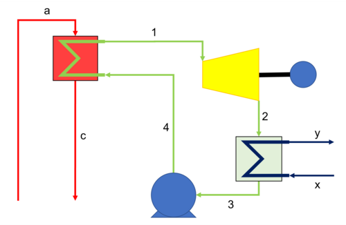
Cold high-pressure working fluid is heated and vapourised in a heat exchanger by the hot geofluid. The hot high-pressure vapour is expanded in a turbine before being cooled and condensed in a condenser. To close the loop, the cold low-pressure liquid is repressurised via a feed pump. The secondary cycle is a closed cycle.
The two main secondary cycle configurations are organic Rankine cycles (ORC) or Kalina cycles, the main difference being the choice of working fluid; an organic fluid (commonly a hydrocarbon or refrigerant) or a water-ammonia mixture respectively.[1]
History
The earliest example of a binary cycle geothermal power plant is thought to have been located on Ischia, Italy, between 1940 and 1943. The plant is thought to have used ethyl chloride as the working fluid at an effective capacity of 250 kW. However, owing to the Second World War taking place at the same time, not much is known about this particular installation.[3]
Another binary cycle geothermal power plant was taken into operation in 1967 near Petropavlovsk on the Kamchatka peninsula, Russia. It was rated at 670 kW and ran for an unknown number of years, proving the concept of binary cycle geothermal power plants.[4]
The first commercial-sized binary cycle geothermal plant was completed in 1979. The 11 MW design by J. Hilbert Anderson Inc. was implemented by Magma Power to harvest power from the hot water fields in East Mesa, Southern California.
As of December 2014, there were 203 binary cycle geothermal power plants across 15 countries worldwide, representing 35% of all geothermal power plants, but only generating 10.4% of total geothermal power (about 1250 MW).[1]
Variations
Dual pressure
The working fluid is evaporated at two different pressure levels, and thus temperatures. This improves efficiency by reducing exergetic losses in the primary heat exchanger by maintaining a closer match between the geofluid cooling curve and the working fluid heating curve.[5]
Dual fluid
Two secondary cycles are operated in tandem, each with a separate working fluid and boiling point. This improves efficiency by reducing the exergetic losses of the heat introduction process, by ensuring a closer match between the geofluid cooling curve and the working fluids' heating curves.[6]
Performance
The performance of a simple binary cycle and its individual components can be calculated as follows:[1]
Turbine

- is the rate of work done by the turbine, in kW
- is the mass flow rate of working fluid, in kg/s
- is the turbine efficiency, non-dimensional
- is the specific enthalpy of the working fluid at the turbine inlet, in kJ/kg
- is the specific enthalpy of the working fluid at the turbine outlet, assuming isentropic expansion in the turbine, in kJ/kg


Condenser
The equation below can be used to determine the condenser duty and mass flow rate of coolant required.

- is the rate of heat removed from the working fluid in the condenser, in kW
- and are the specific enthalpy of the working fluid at the condenser inlet and outlet respectively, in kJ/kg
- is the mass flow rate of coolant, in kg/s
- and are the specific enthalpy of coolant at the condenser inlet and outlet respectively, in kJ/kg


Feed Pump

- is the rate of work done by the pump to repressurise the working fluid, in kW
- is the specific enthalpy of the working fluid at the feed pump outlet, assuming isentropic compression, in kJ/kg
- is the specific enthalpy of the working fluid at the feed pump inlet, in kJ/kg
- is the pump efficiency, non-dimensional


Primary Heat Exchanger
The equation below can be used to determine the primary heat exchanger duty and mass flow rate of geofluid required.

- is the rate of heat added to the working fluid within the primary heat exchanger, kW
- is the specific enthalpy of the working fluid at the primary heat exchanger inlet, in kJ/kg
- is the mass flow rate of geofluid, in kg/s
- and are the specific enthalpy of the geofluid at the primary heat exchanger inlet and outlet respectively, in kJ/kg


Efficiency
There are a number of different definitions of efficiency that may be considered; these are discussed below.[1]
First law efficiency
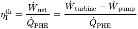
The first law efficiency (from the first law of thermodynamics) is a measure of the conversion of the heat provided to the cycle into useful work. When accounting for real life losses and inefficiencies, real binary cycle geothermal plants have a first law efficiency of between 10 and 13%.[1]
Carnot efficiency
The Carnot efficiency gives the efficiency of an ideal thermodynamic cycle, operating between two reservoirs of different temperatures, as such it provides a theoretical maximum to the efficiency of any heat engine. For this reason, a geothermal power plant producing hot geofluid at 180 °C (≈450 K) and rejecting heat at 25 °C (≈298 K) has a maximum efficiency of just 34%.
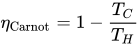
- and are the hot and cold absolute temperature respectively, in K


Second law efficiency
The second law efficiency (from the second law of thermodynamics) is a measure of the utilisation of the ideally maximum work available and conversion into useful work.[1]
![{\displaystyle \eta _{\text{II}}^{\text{util}}={\frac {{\dot {W}}_{\text{net}}}{{\dot {E}}_{\text{geofluid}}}}={\frac {{\dot {W}}_{\text{turbine}}-{\dot {W}}_{\text{pump}}}{{\dot {m}}_{\text{geofluid}}*[(h_{a}-h_{0})-T_{0}*(s_{a}-s_{0})]}}}](https://wikimedia.org/api/rest_v1/media/math/render/svg/e6b5fd6ed39253020a4b31e84ff28dede2797c1c)


Working fluid selection
The working fluid plays a pivotal role in any binary cycle and must be selected with care. Some criteria for selecting a suitable fluid are given below.[1][7]
- A critical temperature and pressure above the cycle maximum temperature and pressure – most of the heat is transferred at the maximum temperature, increasing efficiency.
- A saturation dome that resembles an inverted U – this prevents liquid drop out in the turbine, which reduces efficiency, damages the turbine blades and thus reduces the turbine's lifetime.
- High thermal conductivity – improves the heat transfer in the primary heat exchanger and the condenser, reducing the total heat transfer area required and therefore cost of the plant.
- Environmental compatibility – non-toxic, non-carciogenic, low global warming potential, low ozone depletion potential, non-flammable, chemically inert.
- Low cost and readily available.
Power plants
There are numerous binary cycle power stations in commercial production.
Organic Rankine cycle
- Olkaria III, Kenya[8]
- Mammoth Lakes, California, United States[9]
- Steamboat Springs (Nevada), United States[10]
- Te Huka Power Station, New Zealand[11]
- Kirchstockach (Munich), Germany[12]
- Traunreut, Germany[12]
Kalina cycle
See also
References
- 1234567891011Ronald DiPippo (2016), Geothermal Power Plants: Principles, Applications, Case Studies and Environmental Impact, Butterworth-Heinemann, pp. 193–240, OL 19852678W, Wikidata Q112793147
- ↑ "برنامج تقنيات الطاقة الحرارية الأرضية: أنظمة الطاقة الحرارية المائية" . برنامج تقنيات الطاقة الحرارية الأرضية: التقنيات . وزارة الطاقة الأمريكية، كفاءة الطاقة والطاقة المتجددة (EERE). 2010-07-06 . تاريخ الاسترجاع: 2010-11-02 .
- ↑ رونالد ديبيبو (يناير 2015). "محطات الطاقة الحرارية الأرضية: التطور وتقييمات الأداء". جيوتيرميكس . 53 : 291-307 . doi : 10.1016/J.GEOTHERMICS.2014.07.005 . ISSN 0375-6505 . Wikidata Q112813717 .
- ↑ رونالد ديبيبو (1980)، الطاقة الحرارية الأرضية كمصدر للكهرباء: دراسة عالمية لتصميم وتشغيل محطات الطاقة الحرارية الأرضية ، doi : 10.2172/5165898 ، Wikidata Q112817289
- ↑ رونالد ديبيبو (2008). محطات الطاقة الحرارية الأرضية: المبادئ والتطبيقات ودراسات الحالة والأثر البيئي . أمستردام: باتروورث-هاينمان.
- ↑ "دورة سائلة مزدوجة" . الولايات المتحدة، براءة اختراع رقم 3795103. 1974.
- ↑ تشينجل، يونس أ. ومايكل أ. بولز (2002). الديناميكا الحرارية: منهج هندسي، الطبعة السابعة . بوسطن: ماكجرو هيل. ص. الفصل 10.
- ↑ شركة أورمات تكنولوجيز، "تقنية ثنائية" . تم الاطلاع عليه بتاريخ 30 يونيو 2022 .
- ↑ "محطة ماموث باسيفيك للطاقة الحرارية الأرضية تُكرّم بجائزة بيئية من ولاية كاليفورنيا" . أورمات. 20 أغسطس 2009.
- ↑ "ستيمبوت سبرينغز" .
- ↑ "محطة تي هوكا للطاقة الحرارية الأرضية" . مرصد الطاقة العالمي.
- 1 2 شركة توربودن سبا. "الطاقة الحرارية الأرضية" . تم الاطلاع عليه بتاريخ 30 يونيو 2022 .
- الطاقة الحرارية الأرضية