هذه قائمة بأنابيب التفريغ أو الصمامات الحرارية ، وأنابيب الغاز منخفضة الضغط ، أو أنابيب التفريغ . قبل ظهور أشباه الموصلات، استُخدمت آلاف الأنواع من الأنابيب في الإلكترونيات الاستهلاكية. كما تم إنتاج العديد من الأنابيب الصناعية والعسكرية والمهنية الأخرى. لم يتبقَّ اليوم سوى عدد قليل من الأنواع، تُستخدم بشكل رئيسي في تطبيقات الطاقة العالية والترددات العالية، وكذلك في مضخمات صوت الغيتار عالية الجودة.
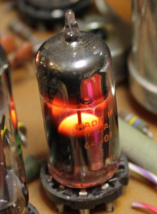
أنبوب تفريغ كهربائي عتيق من نوع جنرال إلكتريك 6CS7 يحمل علامة "تاسا راديوفونيكا".
تصنيفات السخان أو الفتيل
تحتوي صمامات الاستقبال على سخانات أو خيوط تسخين مصممة للتشغيل المباشر بالبطارية، أو التشغيل المتوازي من ملف مخصص على محول تغذية، أو التشغيل المتسلسل في أجهزة بدون محول. أما صمامات طاقة الترددات الراديوية عالية القدرة ، فتُسخّن مباشرةً. يجب أن يكون جهد السخان أقل بكثير من جهد الإشارة على الشبكة، وبالتالي يتراوح بين 5 و25 فولت، ويسحب ما يصل إلى مئات الأمبيرات من محول تسخين مناسب. في بعض سلاسل أرقام أجزاء الصمامات، يُذكر تصنيف جهد السخان في رقم الجزء، وقد يتوفر صمام مماثل بتصنيفات جهد تسخين مختلفة.
FL – هيكل بيضاوي الشكل مصنوع بالكامل من الزجاج، وقواعد مسطحة مزودة بأسلاك توصيل طويلة متصلة مباشرة بالدائرة الكهربائية.
SL – هيكل بيضاوي زجاجي مصغر بالكامل وقواعد مسطحة مزودة بأسلاك توصيل قصيرة يمكن لحامها أو توصيلها بمقبس خاص. (يمكن تقصير أسلاك التوصيل لتناسب المقابس المدمجة).
R8 – جسم وقاعدة دائرية زجاجية بالكامل مصغرة للغاية مع 8 أسلاك توصيل طائرة أو دبابيس صلبة مرتبة في دائرة
أنظمة الترقيم
أنظمة أمريكا الشمالية
نظام أنابيب الاستقبال RETMA
RETMA هو اختصار لجمعية مصنعي أجهزة الراديو والتلفزيون الإلكتروني التي تم تشكيلها في عام 1953 - ومع ذلك، كان المعيار نفسه قيد الاستخدام بالفعل منذ عام 1933، عندما قدمت RCA/Cunningham المعايير 1A6 و2A3 و2A5 وما إلى ذلك.
تمثل المجموعة الأولى من الأحرف رقمًا يمثل جهد التسخين مقربًا إلى أقرب عدد صحيح؛ يشير الرقم 0 إلى أنبوب ذي مهبط بارد . [ 1 ]
حرف أو حرفان مخصصان للأجهزة حسب ترتيب تطويرها.
رقم واحد يمثل عدد العناصر النشطة في الأنبوب.
تُستخدم الأحرف اللاحقة لتمييز المراجعات أو المتغيرات:
أ ، ب ، ج – إصدارات محسّنة متوافقة مع الإصدارات السابقة
GT/G – مصباح زجاجي، مقاس T-9 قابل للتبديل مع النوعين G و GT
L - محلي
LM – معدن محلي
LT – قاعدة القفل
م - ظرف معدني
MG – معدن-زجاج
ML – المعدن المحلي
S - محمي من الرذاذ
W – مُقوّى، أو ذو جودة عسكرية
WA ، WB – إصدارات عسكرية/صناعية محسّنة ومتوافقة مع الإصدارات السابقة
X – قاعدة سيراميكية منخفضة الفقد للاستخدام في الترددات اللاسلكية
Y – قاعدة من راتنج فينولي مملوء بالميكا منخفض الفقد ("ميكانول") للاستخدام في الترددات الراديوية
وأخيرًا، قد يقرر المصنعون دمج رقمين من النوع في اسم واحد، يمكن لجهازهم الواحد أن يحل محله، مثل: 6DX8/ECL84 (حيث أن 6DX8 وECL84 عبارة عن أجهزة متطابقة بموجب أنظمة تسمية مختلفة) أو 6BC5/6CE5 (أجهزة متطابقة بشكل كافٍ ضمن نظام تسمية RETMA) وحتى 3A3/3B2، أو 6AC5-GT/6AC5-G (حيث يحل رقم النوع الواحد، 6AC5-GT/6AC5-G، محل كل من 6AC5-G و6AC5-GT).
غالباً ما تكون التسميات التي تختلف فقط في أرقامها الأولية متطابقة باستثناء خصائص السخان.
استُخدم هذا النظام في الفترة من 1942 إلى 1944، وتم تخصيص أرقام له بالصيغة الأساسية "1A21"، ولذلك يُشار إليه أيضًا باسم "نظام 1A21". [ 1 ] يشير الرقم الأول إلى قدرة التسخين/الفتيل، بينما يُمثل الحرف الثاني رمزًا للوظيفة، أما الرقمان الأخيران فيتم تخصيصهما بالتسلسل، بدءًا من 21.
تم الحفاظ على نظام مكون من أربعة أرقام بواسطة JETEC منذ عام 1944، ثم بواسطة EIA منذ عام 1957 للأنابيب المملوءة بالغاز والفراغ الصناعية والعسكرية والمهنية الخاصة، وجميع أنواع الأجهزة الأخرى التي تتطلب إحكام إغلاقها ضد الغلاف الجوي الخارجي.
بعض الشركات المصنعة كانت تسبق رقم EIA برمز الشركة المصنعة:
حرفان كحد أقصى يشيران إلى نوع البناء وطريقة التبريد:
R أو شرطة (" - ") – غلاف زجاجي، تبريد بالإشعاع
ج - غلاف خزفي
K – (انعكاسي-)كليسترون
P – مخصصة بشكل أساسي لتطبيقات النبض
L – مصعد خارجي، تبريد الحمل الحراري السائل
N – مصعد خارجي، تبريد الهواء بالحمل الحراري الطبيعي
S – مصعد خارجي، تبريد بالتوصيل
V – التبريد بالبخار (يتم غمر الأنود في الماء المغلي، ويتم جمع البخار وتكثيفه وإعادة تدويره)
W – تبريد بالماء (يتم ضخ الماء من خلال غلاف معدني خارجي متصل حرارياً بالأنود)
X – التبريد بالهواء القسري (يتم نفخ الهواء عبر زعانف التبريد المتصلة حرارياً بالأنود)
رقم يشير إلى أقصى تبديد للطاقة في المصعد بالواط. يمكن تجاوز هذا الرقم لفترة قصيرة، طالما لم يتجاوز المتوسط ثابت الزمن الحراري للمصعد (عادةً 0.1 ثانية). في تطبيقات الفئة C ، قد تكون طاقة خرج المضخم المُوَصَّلة إلى الحمل أعلى من تبديد الطاقة في الجهاز.
حرف واحد أو أكثر من الأحرف الخاصة بالشركة المصنعة للدلالة على نوع البناء
3CW5000A3 – صمام ثلاثي سيراميكي بقدرة 5 كيلوواط، مبرد بالماء، من النوع "أ"، مجموعة الكسب 3
3CX100A5 – صمام ثلاثي سيراميكي UHF بقدرة 100 واط، مبرد بالهواء القسري، النوع 'A'، مجموعة الكسب 5؛ يستخدم غالبًا من قبل هواة الراديو لمضخمات الميكروويف في نطاق 23 سم .
3CX1500A7 ( 8877 ) – صمام ثلاثي سيراميكي بقدرة 1.5 كيلو واط، مُبرّد بالهواء القسري، من النوع "أ"، مجموعة الكسب 7
3CX2500A3 – صمام ثلاثي سيراميكي بقدرة 2.5 كيلوواط، مُبرّد بالهواء القسري، من النوع "أ"، مجموعة الكسب 3
4CX35000 - صمام رباعي سيراميكي يستخدم في العديد من أجهزة الإرسال الإذاعية بقدرة 50 كيلو واط، يتم تبريده بالهواء القسري، وغالبًا ما يكون في تكوين دوهرتي كما هو الحال في سلسلة Continental Electronics 317C.
هذا النظام يصف بشكل كبير نوع الجهاز (ثلاثي، ثنائي، خماسي، إلخ) الذي يتم تطبيقه عليه، بالإضافة إلى نوع السخان/الفتيل ونوع القاعدة (ثماني، بيضاوي، إلخ). [ 1 ] [ 3 ] تشمل الشركات المصنعة الملتزمة AEG (de)، وAmperex (الولايات المتحدة)، وCdL (1921، ماركة Mazda الفرنسية )، وCIFTE (الفرنسية، والعلامة التجارية Mazda-Belvu )، و EdiSwan (المملكة المتحدة، والعلامة التجارية Mazda البريطانية )، و Radiotechnique (العلامات التجارية الفرنسية، و Coprim ، و Miniwatt-Dario ، و RTC )، و Lorenz (de)، وMBLE ( fr ، nl ) (be، العلامة التجارية Adzam )، و Mullard (المملكة المتحدة)، و Philips. (nl، العلامة التجارية Miniwatt )، RCA (الولايات المتحدة)، RFT ( de ، sv ) (de) ، Siemens (de)، Telefunken (de)، Tesla (cz)، Toshiba (ja)، Tungsram (hu)، Unitra (العلامات التجارية pl، Dolam ، Polam و Telam ) وValvo ( de ، it ) (de).
أنابيب قياسية
يعود هذا الجزء إلى مفتاح ترميز الصمامات المشترك ( بالألمانية : Röhren - Gemeinschafts schlüssel ) الذي تم التفاوض عليه بين شركتي فيليبس وتليفونكن في الفترة 1933-1934. وكما هو الحال في النظام الأمريكي الشمالي، يصف الرمز الأول جهد التسخين، وهو في هذه الحالة حرف روماني وليس رقمًا. وتصف الأحرف الرومانية اللاحقة، حتى ثلاثة أحرف، الجهاز، متبوعةً برقم واحد إلى أربعة أرقام مُخصصة بترتيب شبه زمني لتطور النوع ضمن نطاقات أرقام مُخصصة لأنواع أساسية مختلفة.
إذا كان لجهازين نفس رمز النوع باستثناء الحرف الأول (مثل ECL82، PCL82، UCL82)، فسيكونان متطابقين عادةً باستثناء مواصفات السخان؛ ومع ذلك، توجد استثناءات، خاصةً مع أنواع المخرجات (على سبيل المثال، يختلف كل من PL84 وUL84 اختلافًا كبيرًا عن EL84 في بعض الخصائص الرئيسية، على الرغم من أن لهما نفس ترتيب الأطراف وقدرة طاقة مماثلة). ومع ذلك، لا تكشف أرقام الأجهزة عن أي تشابه بين عائلات الأنواع المختلفة؛ على سبيل المثال، لا يرتبط قسم التريود في ECL82 بأي من تريودات ECC82، بينما يتشابه قسم التريود في ECL86 مع أقسام التريود في ECC83.
احتفظت شركة برو إلكترون بمجموعة فرعية من نظام MP بعد تأسيسها عام 1966، حيث اقتصرت الأحرف الأولى E و P على السخان، والأحرف الثانية A و B و C و D و E و F و H و K و L و M و Y و Z على النوع، وأصدرت أرقامًا مكونة من ثلاثة أرقام تبدأ من 1 و 2 و 3 و 5 و 8 و 9 للقاعدة. [ 4 ]
ملاحظات: سبقت Tungsram تسمية MP بالحرف T ، كما في TAD1 لـ AD1؛ VATEA Rádiótechnikai és Villamossági Rt.-t. (VATEA Radio Technology and Electric Co. Ltd.، بودابست، هنغاريا) سبقت تسمية MP بالحرف V ، كما في VEL5 لـ EL5.
الحرف الأول: نوع السخان/الفتيل
تُعطى قيم سخانات أنابيب التيار المتردد/المستمر ذات السلسلة المتسلسلة بالمللي أمبير؛ بينما تُعطى قيم سخانات أنابيب التيار المتردد/المستمر ذات السلسلة المتوازية بالفولت.
يتم تسخين بطاريات النيكل والكادميوم مباشرةً بجهد 0.625 فولت تيار مستمر ، كما هو الحال في تصميمات الأنابيب المزدوجة ذات التسخين المتسلسل مثل أجهزة السمع . في حال انقطاع أي من السلكين، يتوقف استنزاف جميع البطاريات [ 5 ].
نطاق واسع من 0.9 فولت إلى 1.55 فولت تيار مستمر، تسخين مباشر للخلايا الجافة
سخان متوازي F – 12.6 فولت تيار مستمر لبطاريات تشغيل المركبات الرصاصية الحمضية ذات 6 خلايا
G – سخانات متنوعة تعمل بجهد يتراوح بين 2.5 و 5.0 فولت تيار متردد (باستثناء 4 فولت) من ملف تسخين منفصل على محول كهربائي رئيسي أو محول ذي خرج أفقي لمقوم جهد الأنود
سخان سلسلة H – 150 مللي أمبير تيار متردد/مستمر
حتى عام 1938 على الأقل: بطارية 4 فولت (مقابل A لـ "4 فولت تيار متردد"؛ لا توجد أمثلة معروفة مُخصصة) [ 6 ] : 2
سخان I – 20 فولت
K – 2.0 فولت سلك تسخين لبطاريات الرصاص الحمضية أحادية الخلية، ولاحقًا لمحولات التيار المتردد
L – سخان سلسلة AC/DC بقدرة 450 مللي أمبير؛ تم نقله إلى هنا من Y
Z – مقوم موجة كاملة فراغي (ثنائي طاقة مزدوج مع كاثود مشترك)
الأرقام التالية: رقم الطراز ونوع القاعدة
بالنسبة للصمامات الخماسية للإشارة، يشير رقم النموذج الفردي في أغلب الأحيان إلى أنبوب ذي تردد قطع متغير ( قطع بعيد )، بينما يشير الرقم الزوجي إلى أنبوب ذي ميل عالٍ (قطع حاد).
بالنسبة لصمامات الطاقة الخماسية ومجموعات الصمام الثلاثي الخماسي، تشير الأرقام الزوجية عادةً إلى الأجهزة الخطية ( مضخمات طاقة الصوت ) بينما كانت الأرقام الفردية أكثر ملاءمة لإشارات الفيديو أو المواقف التي يمكن فيها تحمل المزيد من التشوه.
1-9 – أنابيب بناء من نوع الضغط، معظمها من نوع P8A ذات قاعدة جانبية بثمانية دبابيس (قاعدة P) أو V5A ذات قاعدة جانبية بخمسة دبابيس (قاعدة V) والعديد من التصاميم الأوروبية الأخرى ما قبل الثمانية
10–19 – Y8A قاعدة أنبوب فولاذي بثمانية دبابيس ، والمعروفة أيضًا باسم "الطرف المعدني الألماني الثماني"
20-29 – Loctal B8G ؛ بعض octal ؛ بعض 8-way side contact (باستثناء DAC21 و DBC21 و DCH21 و DF21 و DF22 و DL21 و DLL21 و DM21 التي لها قواعد ثمانية)
50-59 – "أنواع بناء خاصة مزودة بقواعد قابلة للتطبيق على ميزات التصميم المستخدمة"؛ [ 9 ] معظمها قواعد قفل: "لوكتال ذو 9 دبابيس" (B9G) أو لوكتال ذو 8 دبابيس (B8G)؛ ولكنها تستخدم أيضًا لـ Octal وغيرها (زجاج ذو 3 دبابيس؛ ختم قرصي بما في ذلك أنابيب Lighthouse ؛ ألماني ذو 10 دبابيس مع صنبور؛ 4 دبابيس كحد أدنى؛ B26A؛ Magnoval B9D)
60-69 – أنابيب قلم الرصاص – أنابيب زجاجية صغيرة جدًا، ذات نهايات سلكية (أسلاك توصيل متصلة مباشرة بدلاً من الدبابيس)
كانت الصمامات المفرغة التي تتميز بخصائص معينة، وغالبًا ما تكون ذات عمر طويل، خاصةً للاستخدام في أجهزة الكمبيوتر والاتصالات ، تحمل الرقم في اسمها مباشرةً بعد الحرف الأول. وكانت عادةً نسخًا عالية الجودة من الأنواع القياسية. فعلى سبيل المثال، كان E82CC نسخة طويلة العمر من ECC82 مخصصة للاستخدام في أجهزة الكمبيوتر والإشارات العامة، بينما كان E88CC نسخة عالية الجودة من ECC88/6DJ8. أما صمام E80F الخماسي، فكان تطويرًا عالي الجودة لصمام EF80، إلا أنهما لم يكونا متوافقين من حيث الأطراف، ولم يكن بالإمكان استبدالهما دون إعادة توصيل المقبس (ويُستخدم E80F عادةً كبديل عالي الجودة لنوع EF86 المماثل في مضخمات الغيتار). تشير الأحرف "CC" إلى وجود صمامين ثلاثيين، بينما يشير الحرف "F" إلى وجود صمام خماسي واحد داخل هذه الأنواع.
لم يكن لبعض الصمامات الإلكترونية ذات الجودة الخاصة مكافئ قياسي، مثل E55L، وهو صمام خماسي الطاقة واسع النطاق يُستخدم كمرحلة إخراج لمضخمات راسم الإشارة ، وE90CC، وهو صمام ثلاثي مزدوج ذو وصلة كاثود مشتركة وقاعدة سباعية الأطراف يُستخدم في قلابات الاقتران الكاثودي في الحواسيب القديمة. أما E91H فهو صمام سباعي خاص ذو شبكة ثالثة مُخَمَّلة مصممة لتقليل الانبعاث الثانوي؛ وقد استُخدم هذا الجهاز كبوابة، تسمح أو تمنع النبضات المُطبقة على الشبكة الأولى ( التحكم ) عن طريق تغيير الجهد على الشبكة الثالثة، في دوائر الحواسيب القديمة (مشابهة في وظيفتها للصمام الأمريكي 6AS6).
احتوت العديد من هذه الأنواع على دبابيس قاعدة مطلية بالذهب وتكوينات تسخين خاصة داخل أنبوب الكاثود النيكل مصممة لتقليل التشويش الناتج عن مصدر التيار المتردد للتسخين، كما تميزت بعزل أكسيدي مُحسَّن بين السخان والكاثود، مما يسمح برفع جهد الكاثود إلى جهد أعلى من جهد مصدر السخان. (تجدر الإشارة إلى أن رفع جهد الكاثود فوق متوسط جهد السخان، والذي كان يُزوَّد في المعدات المصممة جيدًا من محول ذي ملف ثانوي مؤرض ذي نقطة مركزية، كان أقل ضررًا على العزل الأكسيدي بين السخان والكاثود من خفض جهد الكاثود إلى ما دون جهد السخان، مما يساعد على منع التفاعلات الكيميائية التحليلية الحرارية المعدنية حيث يلامس الأكسيد كاثود النيكل، والتي قد تُشكِّل تنجستات الألومنيوم الموصلة، والتي قد تتطور في النهاية إلى دارة قصر بين السخان والكاثود).
تم استخدام مواد امتصاص محسّنة ، غالباً ما تكون مزدوجة، للحفاظ على فراغ أفضل، كما تم إدخال دعامات أقطاب كهربائية أكثر صلابة للحد من الضوضاء الميكروفونية وتحسين مقاومة الاهتزاز والصدمات. لم تكن فواصل الميكا المستخدمة في النوعين "SQ" و"PQ" تحتوي على نتوءات حادة قد تتقشر وتنفصل داخل المصباح، مما قد يؤدي إلى استقرارها بين الشبكات وبالتالي تغيير خصائص الجهاز. بعض الأنواع، وخاصة E80F وE88CC وE90CC، احتوت على جزء ضيق من المصباح لتثبيت فواصل الميكا المصممة خصيصاً والخالية من التقشر بإحكام. [ 10 ]
لم يتم تبديل القاعدة والوظيفة في الأنابيب ذات الجودة الخاصة اللاحقة ، ولكن تم تخصيص رقم مكون من 4 أرقام لها، [ 3 ] مثل ECC2000 أو ED8000، حيث يشير الرقم الأول منها مرة أخرى إلى القاعدة:
S – عداد/محدد الكاثود المنفصل الذي يجعل جميع الكاثودات متاحة على دبابيس فردية للعرض، عداد/مؤقت/مقسم التردد ، إلخ.
T – صمام ثلاثي مرحل ، ثايراترون ثلاثي منخفض الطاقة ، قطب بدء واحد، قد يحتاج إلى إضاءة للتشغيل السليم إذا لم يتم تحضيره إشعاعيًا
U – ثايراترون رباعي الأقطاب منخفض الطاقة، قد يعني:
قطب تشغيل رباعي ، قطب بدء واحد وقطب تحضير (للحفاظ على التيار) لتوفير الأيونات للحفاظ على جهد الإشعال ثابتًا، لمؤقتات RC التناظرية ، ومحفزات الجهد، وما إلى ذلك.
مرحل رباعي الأقطاب ، قطبان كهربائيان لبدء التشغيل لجعل العدادات ثنائية الاتجاه أو قابلة لإعادة الضبط
R – مقوم التيار، بما في ذلك الأنواع التي يتم التحكم فيها بواسطة الشبكة [ 12 ] [ 13 ]
T – صمام ثلاثي (ترددات الراديو، مذبذب)
X – ثيراترون كبير (بما في ذلك جميع أنواع ثيراترون الهيدروجين والأنواع ذات التيار العالي)
يشير الحرف التالي إلى نوع الفتيل أو الكاثود، أو غاز التعبئة أو تفاصيل أخرى متعلقة بالتصميم. يختلف ترميز أجهزة التفريغ بين شركة فيليبس (وغيرها من الشركات المصنعة في أوروبا القارية) من جهة، وشركتها التابعة مولارد من جهة أخرى.
أ - مهبط الأنتيمون المنشط بالسيزيوم . يُستخدم في المهابط الضوئية ذات الوضع الانعكاسي. نطاق الاستجابة من الأشعة فوق البنفسجية إلى الضوء المرئي. واسع الاستخدام.
C – كاثود السيزيوم على الفضة المؤكسدة، ويسمى أيضًا S1 . نمط الإرسال، حساس من 300 إلى 1200 نانومتر. تيار مظلم عالٍ؛ يستخدم بشكل رئيسي في الأشعة تحت الحمراء القريبة، مع تبريد الكاثود الضوئي.
T – مهبط ثلاثي القلويات من الصوديوم والبوتاسيوم والأنتيمون والسيزيوم، يتميز باستجابة طيفية واسعة من الأشعة فوق البنفسجية إلى الأشعة تحت الحمراء القريبة؛ ويمكن لعملية معالجة خاصة للمهبط أن تمدد النطاق إلى 930 نانومتر. يُستخدم في أجهزة قياس الطيف الضوئي واسعة النطاق .
U – كاثود السيزيوم والأنتيمون مع نافذة كوارتز
يشير الحرف التالي إلى الحشوة:
G – مملوء بالغاز
V – فراغ عالي
يشير الحرف P التالي إلى مضاعف ضوئي.
أمثلة:
50AVP – مضاعف ضوئي ذو 11 مرحلة لعدادات الوميض ، قاعدة اثني عشرية
51UVP – مضاعف ضوئي من 11 مرحلة، قاعدة اثني عشرية
52AVP/XP1180 – مضاعف ضوئي ذو 10 مراحل، قاعدة ذات 13 سنًا
53AVP ، 153AVP – مضاعف ضوئي ذو 10 مراحل، قاعدة ثنائية سباعية ذات 14 دبوسًا
53UVP – مضاعف ضوئي ذو 11 مرحلة، قاعدة ثنائية سباعية ذات 14 دبوسًا
54AVP – مضاعف ضوئي ذو 11 مرحلة، قاعدة ثنائية سباعية ذات 14 دبوسًا
55AVP – مضاعف ضوئي ذو 15 مرحلة، قاعدة ثنائية الاتجاه ذات 20 سنًا
56AVP – مضاعف ضوئي ذو 14 مرحلة، قاعدة ثنائية القطب ذات 20 سنًا
56UVP – مضاعف ضوئي ذو 14 مرحلة، قاعدة اثني عشرية
57AVP – مضاعف ضوئي ذو 11 مرحلة، قاعدة ثنائية الاتجاه ذات 20 سنًا
58AVP – مضاعف ضوئي ذو 14 مرحلة، قاعدة ثنائية الاتجاه ذات 20 سنًا
150AVP – مضاعف ضوئي ذو 10 مراحل، قاعدة ثنائية الاتجاه ذات 20 سنًا
150CVP – مضاعف ضوئي ذو 10 مراحل، قاعدة ثنائية الاتجاه ذات 20 سنًا
57CV – خلية قياس ضوئي
58CG - أنبوب ضوئي مملوء بالغاز، حساس للأشعة الحمراء/الأشعة تحت الحمراء، مصنوع بالكامل من الزجاج ومنتهي بسلك
58CV – أنبوب ضوئي مفرغ، حساس للأشعة الحمراء/الأشعة تحت الحمراء، مصنوع بالكامل من الزجاج وموصل بسلك
90AG – أنبوب ضوئي مملوء بالغاز، حساس لضوء النهار/الأزرق، قاعدة مصغرة ذات 7 دبابيس
90AV – أنبوب ضوئي مفرغ، حساس للون الأزرق، قاعدة مصغرة ذات 7 دبابيس
90CG – أنبوب ضوئي مملوء بالغاز، حساس للأشعة الحمراء/الأشعة تحت الحمراء، قاعدة مصغرة ذات 7 دبابيس
90CV – أنبوب ضوئي مفرغ، حساس للأشعة الحمراء/الأشعة تحت الحمراء، قاعدة مصغرة ذات 7 دبابيس
92AG – أنبوب ضوئي مملوء بالغاز، حساس للون الأزرق، قاعدة مصغرة ذات 7 دبابيس
92AV – أنبوب ضوئي مفرغ، حساس للون الأزرق، قاعدة مصغرة ذات 7 دبابيس
B142 – صمام ثلاثي الطاقة بترددات الراديو بقدرة 400 واط حتى 50 ميجاهرتز، مشابه للصمام 833A
B1109 = 3C24 – صمام ثلاثي القدرة VHF بقدرة 25 واط حتى 60 ميجاهرتز
B1135 = 5867 = CV1350 – صمام ثلاثي القدرة VHF حتى 100 ميجاهرتز
B1152 – صمام ثلاثي الطاقة بترددات الراديو بقدرة 500 واط حتى 50 ميجاهرتز
QT1257 – أنبوب زر لمس ، مفتاح لمس سعوي مضيء ؛ أنبوب مرحل تيار مستمر ذو مهبط بارد ، بادئ تشغيل خارجي (سعوي) يتم تنشيطه باللمس؛ ثم يصبح توهج المهبط مرئيًا. قاعدة ثمانية الأطراف 6-pin
XL601 ، XL602 ، XL603 ، XL627 ، XL628 ، XL631 و XL632 – مصدر ضوء خطي ذو مهبط بارد ( أنبوب معدل التوهج )، ثنائي غازي ذو توهج أزرق بنفسجي، تعديل يصل إلى 1 ميجاهرتز، قاعدة ثمانية الأطراف، لأجهزة استقبال الفاكس ذات الأسطوانة الدوارة ، إلخ.
نظام أنابيب الحوسبة ETL
استخدمت شركة British Ericsson Telephones Limited (ETL)، ومقرها بيستون، نوتنغهام (لا ينبغي الخلط بينها وبين شركة TelefonAB Ericsson السويدية )، وهي المالك الأصلي للعلامة التجارية Dekatron التي أصبحت الآن علامة تجارية عامة ، النظام التالي:
أنبوب تفريغ GD550W – 550 فولت، 1.5 جول، على سبيل المثال لمذبذبات استرخاء الطاقة ، مصنوع بالكامل من الزجاج ومُنهى بسلك
GDT120M – صمام ثلاثي التيار المستمر ذو مهبط بارد مملوء بالغاز 9 مللي أمبير، مزود ببادئ تشغيل واحد وثنائي توهج منفصل يعمل كبادئ ضوئي، قاعدة مصغرة ذات 7 دبابيس
GS12D – عداد/محدد ديكاترون ثنائي عشري مملوء بالنيون، بتردد أقصى 4 كيلو هرتز ، وقاعدة ثنائية عشرية مع طرفين سلكيين إضافيين لأقطاب التوجيه.
GSA10G – عداد/محدد عقدي بتردد أقصى 10 كيلوهرتز، مزود بأدلة توجيه وأقطاب مساعدة لتشغيل أنابيب نيكسي مباشرةً ، قاعدة B27A
GTE120Y – صمام رباعي صغير الحجم يعمل بالتيار المستمر بقدرة 5 مللي أمبير، مزود ببادئ تشغيل واحد ومُشغِّل واحد، جميع أطرافه مصنوعة من أسلاك زجاجية
GTE130T – صمام رباعي الزناد يعمل بتيار مستمر ذروة 8 مللي أمبير ، مزود ببادئ تشغيل واحد ومُهيئ واحد، دقة عالية، مقاومة للتقادم، يعمل في الربع الأول فقط، قاعدة نواة
GTE175M – 3.5 مللي أمبير متوسط ، 50 مللي أمبير ذروة تيار مستمر، رباعي الأقطاب، بادئ تشغيل واحد ومُهيئ واحد، قاعدة مصغرة ذات 7 دبابيس، لدوائر اقتران ديكاترون
GTR120W – صمام ثلاثي صغير الحجم يعمل بتيار مستمر، ذو 3 أطراف زجاجية بالكامل، لتطبيقات الكمبيوتر
يستخدم نظام التسمية البريطاني GEC – Marconi–Osram منذ عشرينيات القرن الماضي حرفًا واحدًا أو حرفين متبوعين برقمين، وأحيانًا بحرف ثانٍ، لتحديد الإصدارات المختلفة من نوع معين. [ 1 ]
تشير الأحرف عمومًا إلى النوع أو الاستخدام:
ملاحظة: يشير الحرف M السابق إلى أنبوب تسخين غير مباشر بجهد 4 فولت تيار متردد
Z77 = 6AM6/EF91 – صمام خماسي الترددات الراديوية ذو القطع الحاد، قاعدة مصغرة ذات 7 دبابيس.
تسميات مولارد قبل عام 1934
كانت أنابيب مولارد القديمة تُصنف في الغالب على أنها PM ، متبوعة برقم يحتوي على جهد الفتيل.
تم ترميز العديد من الصمامات الإلكترونية اللاحقة بحرف أو ثلاثة أحرف شبه بديهية، متبوعة برقم يحتوي على جهد التسخين. وقد تم التخلي عن هذا النظام تدريجياً بعد عام 1934 عندما اعتمدت شركة مولارد نظام مولارد-فيليبس .
1D6 – مقوم نصف موجة ذو تسخين غير مباشر، قاعدة بريطانية بخمسة دبابيس
4D1 – صمام ثلاثي التسخين غير المباشر، قاعدة بريطانية ذات 7 دبابيس
7A3 – صمام خماسي الطاقة ذو التسخين غير المباشر، قاعدة بريطانية ذات 7 دبابيس
8A1 – صمام خماسي ذو قطع حاد للترددات الراديوية، مُسخّن بشكل غير مباشر، قاعدة بريطانية بخمسة دبابيس مع غطاء علوي للأنود
9A1 – صمام خماسي ذو قطع عن بعد بترددات الراديو/الترددات المتوسطة، مُسخّن بشكل غير مباشر، قاعدة بريطانية بخمسة دبابيس مع غطاء علوي للأنود
10D1 – ثنائي مزدوج ذو كاثود مشترك، مُسخّن بشكل غير مباشر، بقاعدة بريطانية خماسية الأطراف
11A2 – ثنائي وثلاثي ذو كاثود مشترك، مُسخّن بشكل غير مباشر، بقاعدة بريطانية ذات 7 دبابيس
13D3 – صمام ثنائي ثلاثي ذو كاثود مشترك، مُسخّن بشكل غير مباشر، قاعدة نوفال
15A2 – محول خماسي الشبكة ذو تسخين غير مباشر، سباعي الأقطاب ، قاعدة بريطانية ذات 7 دبابيس
20D4 – خلاط تردد ثلاثي/سباعي التسخين غير المباشر ، قاعدة نوفال
نظام فالفو قبل عام 1934
كانت شركة Valvo ( de ، it ) شركة ألمانية رئيسية لتصنيع المكونات الإلكترونية من عام 1924 إلى عام 1989؛ وهي شركة تابعة لشركة Philips منذ عام 1927، وكانت Valvo واحدة من الشركات السابقة لشركة NXP Semiconductors .
كان النظام يتألف من حرف أو حرفين متبوعين بثلاثة أو أربعة أرقام. وقد تم التخلي عنه تدريجياً بعد عام 1934 عندما اعتمدت شركة فالفو نظام مولارد-فيليبس .
تتكون تسميات أنابيب الإرسال البولندية Lamina ( pl ) من حرف واحد أو حرفين، ومجموعة من الأرقام وحرف اختياري و/أو رقمين مسبوقين بعلامة "/".
يشير الحرف الأول إلى نوع الأنبوب، بينما يشير حرفان متساويان إلى أنبوب مزدوج:
P - بنتود
كيو – رباعي الأقطاب
T – صمام ثلاثي
تمثل مجموعة الأرقام الحد الأقصى لتبديد طاقة الأنود بالكيلوواط
يُحدد حرف اختياري طريقة التبريد:
<لا شيء> – الإشعاع
P – هواء قسري
W - ماء
الرقم الأول من الرقمين اللذين يليان علامة "/" يعني:
1- أنبوب لأجهزة البث الإذاعي والاتصالات اللاسلكية
2- أنبوب للمعدات الصناعية
3- أنبوب يستخدم في معدات البث التلفزيوني
4- أنبوب لمعدات الاتصالات اللاسلكية ذات التعديل غير المتوازن
5- مُعدِّل أو أنبوب نبضي
يتم تعيين الرقم الثاني بعد علامة "/" بالتسلسل.
أمثلة:
Q01 – صمام رباعي الطاقة يصل إلى 125 ميجاهرتز، 0.1 كيلو واط (=100 واط)
Q3.5 – صمام رباعي الطاقة يصل تردده إلى 220 ميجاهرتز، 3.5 كيلوواط
QQ-004/11 – صمام رباعي الطاقة مزدوج الحزمة يصل إلى 500 ميجاهرتز، 0.04 كيلو واط (=40 واط)
T01 – صمام ثلاثي القدرة يصل تردده إلى 200 ميجاهرتز، وقدرته 135 واط
T015/21 – صمام ثلاثي القدرة يصل تردده إلى 150 ميجاهرتز، وقدرته 150 واط
T02 – صمام ثلاثي القدرة يصل تردده إلى 60 ميجاهرتز، 200 واط
T05P/31 – صمام ثلاثي الطاقة مبرد بالهواء القسري حتى 1 جيجاهرتز، 1 كيلوواط
T2/22 – صمام ثلاثي القدرة يصل تردده إلى 60 ميجاهرتز، 3 كيلوواط
T6 – صمام ثلاثي القدرة يصل تردده إلى 30 ميجاهرتز، 6 كيلوواط
T8P/21 – صمام ثلاثي الطاقة مبرد بالهواء القسري يصل تردده إلى 120 ميجاهرتز، وقدرته 8 كيلوواط
T10P/22 – صمام ثلاثي القدرة يصل تردده إلى 30 ميجاهرتز، وقدرته 10 كيلوواط
T-25P – صمام ثلاثي الطاقة مبرد بالهواء القسري بتردد يصل إلى 30 ميجاهرتز، 25 كيلوواط
T60W/21 – صمام ثلاثي الطاقة مبرد بالماء يصل تردده إلى 30 ميجاهرتز، وقدرته 6 كيلوواط
نظام أنابيب الإرسال RFT
كانت شركة Rundfunk- und Fernmelde-Technik ( بالألمانية: Éd , sv ) علامة تجارية لمجموعة من مصنعي أجهزة الاتصالات في جمهورية ألمانيا الديمقراطية. ويتكون اسمها من ثلاثة أحرف وثلاثة أو أربعة أرقام.
يحدد الحرفان الأولان نوع الأنبوب:
GR – أنبوب مقوم
SR – أنبوب الإرسال
VR – أنبوب مكبر الصوت
الحرف الثالث يحدد طريقة التبريد:
L – هواء قسري
S – الإشعاع
V – البخار (يتم غمر المصعد في الماء المتبخر، ويتم جمع البخار وتكثيفه وإعادة تدويره)
W - ماء
يشير الرقم الأول (أو أول رقمين في الأنابيب المزدوجة) إلى عدد الأقطاب الكهربائية:
2 – الصمام الثنائي
3 – الصمام الثلاثي
4 – رباعي الأقطاب
5 – بنتود
يتم تعيين الرقمين الأخيرين بالتسلسل.
أمثلة:
SRS301 – صمام ثلاثي مبرد بالإشعاع يصل تردده إلى 40 ميجاهرتز، وقدرته 900 واط
SRS464 – صمام رباعي نبضي مبرد بالإشعاع ومقاوم للاهتزازات بقدرة تصل إلى 300 كيلوواط
SRS4451 – صمام رباعي مزدوج مبرد بالإشعاع يصل تردده إلى 500 ميجاهرتز، وقدرته 60 واط
SRS4452 = QQE03/20 = 6252 – صمام رباعي مزدوج مبرد بالإشعاع يصل تردده إلى 600 ميجاهرتز، وقدرته 20 واط
SRS4452 – صمام رباعي مزدوج مبرد بالإشعاع يصل تردده إلى 600 ميجاهرتز، وقدرته 20 واط
SRS501 – صمام خماسي مبرد بالإشعاع يصل تردده إلى 50 ميجاهرتز، وقدرته 100 واط
SRS552N = ГУ-50 – صمام خماسي مبرد بالإشعاع يصل تردده إلى 120 ميجاهرتز، وقدرته 50 واط
الرقم التالي: تبديد الطاقة عند المصعد بالواط (في حالة التبريد بالإشعاع) أو بالكيلوواط (في حالة عدم التبريد).
الحرف التالي يحدد طريقة التبريد:
<لا شيء> – الإشعاع
V – بخار
X – هواء قسري
Y - ماء
أمثلة:
RA0007B – ثنائي كبح ذو انبعاث مشبع مُسخّن مباشرةً . يعمل كمقاومة توالي متغيرة يتم التحكم فيها بتيار التسخين في دوائر مُثبّت الجهد/التيار؛ U Amax 600 فولت I Amax 700 ميكرو أمبير، قاعدة نوفال
RA100A – مقوم نصف موجة 40 كيلو فولت، 100 مللي أمبير، مزود بقاعدة مصباح لولبية من نوع E40 غولياث إديسون وغطاء علوي للأنود
RC5B – صمام ثلاثي الطاقة من نوع الكأس UHF بقدرة تصل إلى 5 واط
RD27AS – صمام ثلاثي الطاقة مبرد بالإشعاع يصل تردده إلى 25 ميجاهرتز، وقدرته 27 واط
RD200B – صمام ثلاثي الطاقة مبرد بالإشعاع يصل تردده إلى 60 ميجاهرتز، وقدرته 200 واط
RD300S – صمام ثلاثي الطاقة مبرد بالإشعاع يصل تردده إلى 200 ميجاهرتز، وقدرته 300 واط
RD150YA – صمام ثلاثي الطاقة مبرد بالماء يصل تردده إلى 3 ميجاهرتز، وقدرته 150 كيلوواط
RE65A – صمام رباعي شعاعي مبرد بالإشعاع يصل تردده إلى 260 ميجاهرتز، 65 واط
RE125C – صمام رباعي شعاعي مبرد بالإشعاع يصل تردده إلى 235 ميجاهرتز، وقدرته 125 واط
RE400C – صمام رباعي شعاعي مبرد بالإشعاع يصل تردده إلى 235 ميجاهرتز، وقدرته 400 واط
RE20XL – صمام رباعي شعاعي مبرد بالهواء يصل تردده إلى 220 ميجاهرتز، وقدرته 20 كيلوواط
REE30A – صمام رباعي مزدوج الحزمة مبرد بالإشعاع يصل تردده إلى 250 ميجاهرتز، 20 واط
RL15A – صمام خماسي الطاقة مبرد بالإشعاع يصل تردده إلى 60 ميجاهرتز، وقدرته 20 واط
RL40A – صمام خماسي الطاقة مبرد بالإشعاع يصل تردده إلى 120 ميجاهرتز، وقدرته 40 واط
RL65A – صمام خماسي الطاقة مبرد بالإشعاع يصل تردده إلى 15 ميجاهرتز، وقدرته 65 واط
UA025A – مقوم نصف موجة مملوء بغاز الأرجون، بجهد 10 كيلو فولت وتيار 250 مللي أمبير، مزود بقاعدة مصباح لولبية من نوع E27 وغطاء علوي لولبي للأنود
UA5A – مقوم بخار الزئبق نصف موجة 11 كيلو فولت، 5 أمبير، بقاعدة ثنائية الأطراف وغطاء علوي لولبي للأنود
ZD1000F – صمام ثلاثي الطاقة مبرد بالإشعاع يصل تردده إلى 60 ميجاهرتز، وقدرته 1 كيلوواط
ZD1XB – صمام ثلاثي الطاقة AF مبرد بالهواء بقدرة تصل إلى 1.2 كيلو واط
ZD3XH – صمام ثلاثي الطاقة مبرد بالهواء يصل تردده إلى 60 ميجاهرتز، وقدرته 3 كيلوواط
ZD8XA – صمام ثلاثي الطاقة مبرد بالهواء يصل تردده إلى 20 ميجاهرتز، وقدرته 8 كيلوواط
ZD12YA – صمام ثلاثي الطاقة AF مبرد بالهواء يصل تردده إلى 20 ميجاهرتز، وقدرته 12 كيلوواط
ZE025XS – صمام رباعي شعاعي مبرد بالهواء يصل تردده إلى 400 ميجاهرتز، بقدرة 250 واط
نظام أنابيب استقبال تونغسرام قبل عام 1934
كان نظام تونغسرام يتألف من ثلاثة أحرف كحد أقصى وثلاثة أو أربعة أرقام. [ 25 ] [ 24 ] وقد تم التخلي عنه تدريجياً بعد عام 1934 عندما اعتمدت تونغسرام نظام مولارد-فيليبس ، وغالباً ما كان يسبقه الحرف T ، كما في TAD1 لـ AD1.
الحرف: نوع النظام:
ملاحظة: يشير الحرف A السابق إلى أنبوب مُسخَّن بشكل غير مباشر
D – ثنائي كاشف
DD – ثنائي مزدوج
DG – رباعي الأقطاب مع شبكة شحنة فضائية (الشبكة الثانية هي شبكة التحكم)
تُصنّع أنابيب التفريغ في الاتحاد السوفيتي السابق وفي روسيا الحالية باستخدام الأحرف السيريلية. وقد نشأ بعض الالتباس عند ترجمة هذه التسميات إلى اللاتينية.
تم تقديم النظام الأول في عام 1929. وكان يتألف من حرف واحد أو حرفين (يشيران إلى نوع النظام، ونوع الكاثود اختيارياً)، وشرطة، ثم رقم متسلسل يصل إلى 3 أرقام. [ 24 ]
في عام 1937، اشترى الاتحاد السوفيتي خط تجميع أنابيب من شركة RCA (التي كانت تواجه آنذاك صعوبات في جمع الأموال اللازمة لعملياتها الأساسية)، بما في ذلك تراخيص الإنتاج والتدريب الأولي للموظفين، وقام بتركيبه في مصنع سفيتلانا في سانت بطرسبرغ، روسيا. ومنذ ذلك الحين، تم إنتاج أنابيب مرخصة من الولايات المتحدة بموجب نظام RETMA معدل .
في الخمسينيات من القرن العشرين، تم اعتماد نظام مكون من 5 عناصر ( بالروسية : Го сударственный Ст андаart "معيار الدولة" ГОСТ/ GOST 5461–59، لاحقًا 13393–76) في الاتحاد السوفيتي (آنذاك) لتعيين الأنابيب المفرغة لجهاز الاستقبال. [ 27 ] [ 28 ]
العنصر الأول هو رقم يحدد جهد الفتيل. العنصر الثاني هو حرف سيريلّي يحدد نوع الجهاز. العنصر الثالث هو رقم تسلسلي يُميّز بين الأجهزة المختلفة من النوع نفسه. العنصر الرابع يُشير إلى نوع الغلاف. أما العنصر الخامس الاختياري فيتكون من شرطة متبوعة بحرف واحد أو أكثر للدلالة على خصائص خاصة للأنبوب. وهذا عادةً ما يُشير إلى اختلافات في التصميم، وليس مجرد اختياره من إنتاج ذي جودة عادية.
أنظمة أنابيب احترافية
يوجد نظام تسمية آخر للأنابيب الاحترافية مثل أنابيب الإرسال. [ 29 ] [ 24 ]
يُحدد العنصر الأول الوظيفة. أما العناصر التالية فتختلف في تفسيرها. بالنسبة لأنابيب الإغنيترون والمقومات والثايراترون، يوجد رقم، ثم شرطة، ثم تيار المصعد بالأمبير، ثم شرطة مائلة، ثم جهد المصعد بالكيلوفولت. قد يُضاف حرف للدلالة على التبريد بالماء (لا يُضاف حرف للدلالة على جهاز مُبرد بالإشعاع). بالنسبة لأنابيب الإرسال في هذا النظام، يبدأ العنصر الثاني بشرطة، ثم رقم مُتسلسل، ثم حرف اختياري يُحدد طريقة التبريد. أما بالنسبة للأنابيب الضوئية والمضاعفات الضوئية، فيكون العنصر الثاني رقمًا مُتسلسلًا، ثم رمزًا حرفيًا يُحدد نوع التعبئة (فراغ أو غاز) ونوع المهبط.
6G-E12A – مؤشر ضبط ثنائي القنوات من نوع "العين السحرية" ، هدف مستطيل
6H-B26 – أنبوب طاقة الشعاع
6M-DE1 – مؤشر ضبط من نوع الصمام الثنائي و"العين السحرية"، قاعدة مصغرة ذات 7 دبابيس
6M-E4 - مؤشر ضبط من نوع "الإصبع السحري"، قاعدة مصغرة ذات 7 دبابيس
6M-E5 = 6ME5 – مؤشر ضبط من نوع "العين السحرية"، قاعدة مصغرة ذات 7 دبابيس
6M-E10 – مؤشر ضبط من نوع "العين السحرية"، قاعدة مصغرة ذات 7 دبابيس
6N-H10 – نوفيستور
6R-A8 – صمام ثلاثي القدرة
6R-B10 – أنبوب طاقة الشعاع
6R-B11 – أنبوب طاقة الشعاع
أنظمة التسمية العسكرية
أنظمة تسمية المركبات التجارية البريطانية وطائرات M8000
يُضيف هذا النظام الأحرف "CV" قبل رقم مكون من ثلاثة أو أربعة أرقام، وتعني "صمام مدني"، أي أنه مشترك بين جميع فروع القوات المسلحة الثلاثة. وقد طُبّق هذا النظام خلال الحرب العالمية الثانية لتوحيد التسميات السابقة التي كانت تُدار بشكل منفصل من قِبل وزارة الحرب/وزارة التموين، ووزارة البحرية، ووزارة الطيران/وزارة إنتاج الطائرات نيابةً عن فروع القوات المسلحة الثلاثة (مثل "ACR~" و"AR~" و"AT~" وما إلى ذلك لصمامات CRT ، وهي صمامات استقبال وإرسال تُستخدم في معدات الجيش، و"NC~" و"NR~" و"NT~" بالمثل لمعدات البحرية، و"VCR~" و"VR~" و"VT~" وما إلى ذلك لمعدات القوات الجوية)، حيث كان من الممكن من حيث المبدأ تطبيق ثلاثة تسميات منفصلة على الصمام نفسه (والذي غالبًا ما كان له تسمية تجارية نموذجية واحدة على الأقل). تتطابق هذه الأرقام عمومًا في كل من نظامي أمريكا الشمالية (RETMA) وأوروبا الغربية (Mullard-Philips)، لكنها لا تُشبه رقم "CV" المُخصص.
أمثلة:
CV1988 = 6SN7 GT = ECC32 (ليس مكافئًا مباشرًا لأن تيار التسخين مختلف والمصباح أكبر)
CV2729 = E80F – نسخة SQ من EF80 ولكن مع ترتيب دبابيس مُعدّل وشاشة أساسية مُستبدلة بشاشة الترددات اللاسلكية
تشير أرقام "CV4000" إلى الصمامات ذات الجودة الخاصة، على الرغم من أن صمامات SQ التي تحمل أرقام CV قبل دخول هذه القاعدة حيز التنفيذ تحتفظ برقم CV الأصلي الخاص بها:
يشير الرمز "M8" في رقم القطعة إلى أنها طُورت من قبل الجيش:
M8083 – صمام خماسي ذو قطع حاد، قاعدة مصغرة ذات 7 دبابيس (إصدار SQ من EF91 = 6AM6 = Z77)
M8162 = 6060 – ثنائي ثلاثي عالي التضخيم، للاستخدام كمضخم/خلاط ترددات الراديو في دوائر VHF، قاعدة نوفال (إصدارات SQ من ECC81 = 12AT7 = B309)
تم اعتماد مبدأ نظام ترقيم صمامات التحكم (CV) أيضًا في نظام الترقيم المشترك للجيش والبحرية الأمريكية (JAN)، والذي تم توسيعه لاحقًا بشكل كبير ليصبح نظام أرقام المخزون الفيدرالي الأمريكي، ثم نظام أرقام المخزون الخاص بحلف الناتو، والذي تستخدمه جميع دول الحلف. يضمن نظام تعريف القطع هذا حصول كل قطعة غيار (وليس فقط الصمامات الحرارية) على رقم مخزون فريد في جميع أنحاء حلف الناتو، بغض النظر عن مصدرها، وبالتالي لا يتم تخزينها بشكل غير فعال في مخازن منفصلة. في حالة صمامات التحكم، يكون رقم المخزون دائمًا بالصيغة 5960-99-000-XXXX، حيث يمثل XXXX رقم صمام التحكم (مع إضافة صفر في البداية إذا كان رقم صمام التحكم مكونًا من 3 أرقام فقط).
أنظمة التسمية الأمريكية
يستخدم أحد الأنظمة الأحرف "VT" قبل رقم مكون من ثلاثة أرقام، ويُفترض أنها تعني "أنبوب مفرغ". بينما تستخدم أنظمة أخرى الأحرف "JHS" أو "JAN" قبل الرقم. ويمكن أن تكون الأرقام التي تلي هذه الأحرف أرقامًا "خاصة" مكونة من أربعة أرقام، أو أرقامًا محلية مكونة من رقمين أو ثلاثة أرقام، أو ببساطة نظام الترقيم المحلي لأمريكا الشمالية "RETMA". وكما هو الحال في النظام العسكري البريطاني، فإن لهذه الأنظمة العديد من المكافئات المباشرة في الأنظمة المدنية. ومن المثير للارتباك أن البريطانيين كان لديهم أيضًا نظامان مختلفان تمامًا لتسمية "VT"، أحدهما يستخدمه سلاح الجو الملكي (انظر القسم السابق)، والآخر يستخدمه مكتب البريد العام ، المسؤول عن البريد والاتصالات في ذلك الوقت، حيث ربما كانت تعني "صمام، هاتف"؛ ولم يكن أي من هذه الأنظمة متوافقًا مع الآخر بأي شكل من الأشكال.
أمثلة:
أنظمة ترقيم "VT"
معدل VT90 في أمريكا الشمالية = 6H6
جهاز الإرسال VHF البريطاني (سلاح الجو الملكي البريطاني) VT90 - صمام ثلاثي
البريطاني (GPO) VT90 = ML4 = CV1732 – صمام ثلاثي القدرة
VT104 – صمام خماسي الترددات الراديوية
VT105 – صمام ثلاثي الترددات الراديوية
أنظمة أخرى تعتمد على الأرقام فقط
توجد أنظمة ترقيم رقمية متعددة، تُستخدم عادةً للأجهزة المستخدمة في المعدات التجارية أو الصناعية. يعود تاريخ أقدم أنظمة الترقيم إلى أوائل عشرينيات القرن الماضي، مثل نظام الترقيم الثنائي، بدءًا من جهاز UV-201A الذي كان يُعتبر "النوع 01"، واستمر استخدامه بشكل شبه متواصل حتى ثمانينيات القرن الماضي. حافظت شركة RCA على أنظمة الترقيم الثلاثية والرباعية ، واعتمدتها أيضًا العديد من الشركات المصنعة الأخرى، وشملت عادةً أجهزة التقويم وأجهزة إخراج الإرسال اللاسلكي. تميل الأجهزة التي تحمل أرقامًا في نطاق 800 إلى أن تكون من نوع أجهزة إخراج الإرسال، بينما لا تُعدّ الأجهزة التي تحمل أرقامًا في نطاق 800 الأعلى أنابيب مفرغة، بل مقومات مملوءة بالغاز وثايراترونات ، أما الأجهزة التي تحمل أرقامًا في نطاق 900 فتميل إلى أن تكون أجهزة ذات أغراض خاصة وعالية التردد. لم يكن استخدام هذه الأنظمة منهجيًا بشكل صارم، فقد كان للجهاز 807 متغيرات هي 1624 و1625 و807W.
حرف آخر متبوع بأرقام
توجد العديد من هذه الأنظمة من مناطق جغرافية مختلفة، مثل تلك المستخدمة في الأجهزة المصنعة في روسيا والصين. كما استُخدمت أنظمة ترقيم مركبة أخرى لتمييز الأنواع ذات الموثوقية العالية المستخدمة في التطبيقات الصناعية أو التجارية. كذلك، تطلبت أجهزة الكمبيوتر ومعدات الاتصالات أنابيب ذات جودة وموثوقية أعلى من تلك المستخدمة في الأجهزة المنزلية والاستهلاكية.
بعض الأحرف التي تبدأ بها الرموز هي رموز خاصة بالشركة المصنعة:
تُستمد بعض التسميات من سلوك الأجهزة التي تعتبر استثنائية.
باعت مازدا/إديسوان أنابيبها الأولى لتسخين محول التيار المتردد الرئيسي 4 فولت (على عكس بطارية التخزين المنزلية) مع البادئة AC/ (للاطلاع على أمثلة انظر أدناه ).
أول صمامات رباعية الشعاع المصنعة في المملكة المتحدة في أواخر الثلاثينيات من القرن العشرين بواسطة M-OV ، تحمل بادئة "KT" التي تعني صمام رباعي بدون انحناء (للاطلاع على أمثلة انظر أعلاه ).
تعمل بطريقة مشابهة لثنائي زينر ، ولكن عند الفولتيات العالية. يشير ترتيب الأحرف (ABC) إلى زيادة تصنيفات الفولتية على منظمات الجهد الثمانية وتناقص تصنيفات الفولتية على منظمات الجهد المصغرة.
0A2 – منظم جهد 150 فولت، قاعدة مصغرة ذات 7 دبابيس
0A3 - منظم جهد 75 فولت، قاعدة ثمانية، يُعرف أيضًا باسم VR75
0B2 – منظم جهد 105 فولت، قاعدة مصغرة ذات 7 دبابيس
0B3 – منظم جهد 90 فولت، قاعدة ثمانية، يُعرف أيضًا باسم VR90
0C2 – منظم جهد 75 فولت، قاعدة مصغرة ذات 7 دبابيس
0C3 – منظم جهد 105 فولت، قاعدة ثمانية، يُعرف أيضًا باسم VR105
0D3 – منظم جهد 150 فولت، قاعدة ثمانية، يُعرف أيضًا باسم VR150
أنابيب أخرى ذات مهبط بارد
0A4G – متوسط تيار 25 مللي أمبير ، ذروة تيار 100 مللي أمبير. صمام ثلاثي غازي مصمم للاستخدام كمستقبل للتحكم في التموج ؛ عند توصيل الكاثود بنقطة المنتصف لدائرة رنين LC متسلسلة عبر التيار الكهربائي المباشر، فإنه يقوم بتنشيط مرحل في دائرة الأنود الخاصة به أثناء وجود تيار كهربائي نشط.
0Y4 – 40 ≤ I ≤ 75 مللي أمبير، مقوم غاز نصف موجة مزود بقطب بدء التشغيل، قاعدة ثمانية الأطراف 5 دبابيس
0Z4 – 30 ≤ I ≤ 90 mA مقوم غازي كامل الموجة مملوء بغاز الأرجون، بقاعدة ثمانية. يستخدم على نطاق واسع في مصادر طاقة المهتزات في أجهزة استقبال الراديو القديمة للسيارات.
أنابيب التسخين/الفتيل بجهد 1 فولت
أنابيب صغيرة الحجم تعمل بفتيلة تيار مستمر بجهد 1.25 فولت
استُخدمت الأنابيب التالية في أجهزة الاتصال اللاسلكي وأجهزة الراديو المحمولة صغيرة الحجم بعد الحرب العالمية الثانية. جميعها مزودة بفتائل تيار مستمر بجهد 1.25 فولت ومهابط مُسخّنة مباشرة. يُحدد بعضها أي طرف من الفتيلة يُغذّى بالجانب الموجب لمصدر طاقة الفتيلة (عادةً بطارية). جميعها ذات أجسام زجاجية يتراوح عرضها بين 7.2 و10.2 مليمتر ، وطولها الإجمالي بين 32 و51 مليمتر .
1A3 – ثنائي عالي التردد ذو مهبط مسخن بشكل غير مباشر. يستخدم ككاشف في بعض أجهزة استقبال AM/FM المحمولة.
1A7GT/DK32 - محول Pentagrid ، نسخة معاد هندستها من النوعين 1A6 و 1D7-G ، مصممة للاستخدام في أجهزة الراديو المحمولة AC/DC/Dry-cell التي تم طرحها في عام 1938. يحتوي على فتيل 1.4 فولت/50 مللي أمبير.
1B7-GT – نسخة مُعاد هندستها من النوعين 1C6 و 1C7-G ، مُصممة للاستخدام في أجهزة الراديو التي تعمل ببطاريات الخلايا الجافة ذات نطاقات الموجات القصيرة. تحتوي على فتيل 1.4 فولت/100 مللي أمبير.
1G6-G – صمام ثلاثي مزدوج القدرة. يتوفر أيضًا إصدار "GT".
1L6 – مُبدِّل تردد خماسي الشبكة لأجهزة الراديو التي تعمل بالبطارية معفتيل 50 مللي أمبير
1LA6 (لوكتال) ولاحقًا 1L6 (مصغر ذو 7 دبابيس) – محول خماسي الشبكة يعمل بالبطارية لراديو الموجات القصيرة زينيث ترانس أوشيانيك ، 50 مللي أمبير فتيل
1LB6 – خلاط سوبر هيتروداين لأجهزة الراديو التي تعمل بالبطارية
1S4 – مضخم طاقة خماسي من الفئة A ، جهد الأنود في نطاق 45...90 فولت.
1S5 – صمام خماسي حاد القطع من الفئة A، ومضخم ثنائي، يُستخدم ككاشف ومرحلة الصوت الأولى في أجهزة استقبال الراديو التي تعمل بالبطارية. جهد الأنود يتراوح بين 67 و90 فولت.
1T4/DF91 – مضخم RF Pentode من الفئة A ذو قطع عن بعد، قاعدة مصغرة ذات 7 دبابيس، يستخدم كمضخم RF و IF في أجهزة استقبال الراديو التي تعمل بالبطارية.
1U4 – مضخم RF Pentode ذو القطع الحاد من الفئة A، قاعدة مصغرة ذات 7 دبابيس، يستخدم كمضخم RF و IF في أجهزة استقبال الراديو التي تعمل بالبطارية، خصائص مشابهة لـ 6BA6.
1U6 - مطابق تقريبًا للنوع 1L6 ، ولكن بفتيل 1.4 فولت/25 مللي أمبير
البادئة "1" لأجهزة الاستقبال المنزلية
صُنعت هذه الأنابيب لأجهزة استقبال بطاريات التخزين المنزلية التي تم تصنيعها خلال أوائل إلى منتصف ثلاثينيات القرن العشرين؛ جميعها مزودة بفتائل تيار مستمر بجهد 2.0 فولت على الرغم من البادئة 1، والتي تهدف إلى تمييزها عن الأنابيب المسخنة بتيار متردد بجهد 2.5 فولت المدرجة أدناه
1A4-p – صمام خماسي ذو قطع عن بعد
1A4-t – صمام رباعي ذو قطع عن بعد
1A6 – محول خماسي الشبكة بتردد يصل إلى 10 ميجاهرتز فقط نظرًا لانخفاض طاقة التسخين (2 فولت/60 مللي أمبير) وما يترتب على ذلك من انخفاض الانبعاث في قسم المذبذب؛ كما يُستخدم أحيانًا ككاشف لتسرب الشبكة
1B4-p – صمام خماسي ذو قطع حاد
1B4-t – صمام رباعي ذو قطع حاد
1B5 – ثنائي كاشف مزدوج، ثلاثي متوسط الميكرو . عادةً ما يكون مرقمًا 1B5/25S
1C5 – صمام خماسي الطاقة (مشابه لـ 3Q5 باستثناء الفتيل)
1C6 - محول خماسي الشبكة؛ 1A6 ، مع ضعف قدرة التسخين وضعف نطاق التردد
1C7-G – نسخة ثمانية من النوع 1C6 .
1D5-Gp – نسخة ثمانية من النوع 1A4-p .
1D5-Gt – نسخة ثمانية من النوع 1A4-t . ( ملاحظة: هذا ثماني "G" ذو كتف، وليس ثماني "GT" أسطواني.)
1D7-G – نسخة ثمانية من النوع 1A6 .
1E5-Gp – نسخة ثمانية من النوع 1B4-p .
1E5-Gt – نسخة ثمانية من النوع 1B4-t . ( ملاحظة: هذا ثماني "G" ذو كتف، وليس ثماني "GT" أسطواني.)
1E7-G - صمام خماسي مزدوج القدرة للاستخدام كمحرك عند التوصيل بالتوازي، أو كمخرج دفع-سحب. يتوفر أيضًا إصدار "GT".
1F4 – صمام خماسي القدرة
1F5-G – النسخة الثمانية من 1F4 .
1F6 – ثنائي مزدوج، خماسي ذو قطع حاد
1F7-G – النسخة الثمانية من النوع 1F6
1G4-GT/G – صمام ثلاثي ثماني، معامل التضخيم 8.8
1G5-G – صمام خماسي الطاقة
1H4-G – صمام ثلاثي متوسط الميكرو، يمكن استخدامه كصمام ثلاثي للطاقة. نسخة ثمانية من النوع 30 ، وهو نسخة مطورة من النوع 01-A . يتوفر أيضًا إصدار "GT".
1H6-G – نسخة ثمانية من النوع 1B5/25S . يتوفر أيضًا إصدار "GT".
1J5-G (950) – خماسي طاقة التركيز البؤري التلقائي
1J6-G – صمام ثلاثي مزدوج القدرة، نسخة ثمانية من النوع 19. يتوفر أيضًا إصدار "GT".
مقومات الأنود لأنابيب أشعة الكاثود
1G3GT – مقوم عالي الجهد ثماني الأقطاب. له نفس خصائص 1B3GT. العديد من هذه المقومات مدرجة ومصنفة تحت اسم 1B3GT/1G3GT.
1J3GT – مقوم ثماني عالي الجهد. له نفس خصائص 1B3GT. مزود بحماية من قصر الدائرة بين الفتيل والصفيحة. يُدرج ويُصنف العديد منه تحت اسم 1J3GT/1K3GT.
1K3GT – مقوم عالي الجهد ثماني الأقطاب. له نفس خصائص 1B3GT. مزود بحماية من قصر الدائرة بين الفتيل والصفيحة. يُدرج ويُصنف العديد منه تحت اسم 1J3GT/1K3GT.
1S2A – مقوم نوفال عالي الجهد بفتيلة 1.4 فولت/550 مللي أمبير. مشابه لـ DY86 وDY87 وDY802 و1R10 و1R12.
1T2 = R16 – مقوم جهد عالي مصغر للغاية بفتيلة 1.4 فولت/140 مللي أمبير. يحتوي على أسلاك مرنة.
1V2 – مقوم عالي الجهد بفتيلة 0.625 فولت/300 مللي أمبير، قاعدة مصغرة ذات 7 دبابيس
1X2 – مقوم نوفال عالي الجهد بفتيلة 1.25 فولت/200 مللي أمبير. 1X2A و1X2B و1X2C مزودة بدرع واقٍ من الأشعة السينية. مشابه لـ DY80 وR19.
1Y2 – مقوم عالي الجهد ذو 4 أطراف، بفتيلة 1.5 فولت/290 مللي أمبير. أقصى جهد عكسي 50 كيلو فولت، ذروة التيار 10 مللي أمبير، متوسط التيار 2 مللي أمبير. قابل للاستخدام حتى 1 ميجاهرتز.
1Z1 – مقوم ثماني عالي الجهد مع فتيل 0.7 فولت / 180 مللي أمبير.
1Z2 – مقوم نوفال عالي الجهد مع فتيل 1.25 فولت / 265 مللي أمبير.
1AD2 – مقوم كومباكترون عالي الجهد بفتيلة 1.25 فولت/200 مللي أمبير. النوع 1AD2A مزود بدرع واقٍ من الأشعة السينية.
1AY2 – مقوم جهد عالي ذو قاعدة ثنائية الأطراف "Duopin". له خصائص كهربائية مشابهة لـ 1B3GT.
1B3GT - ثنائي مقوم عالي الجهد ثماني الأقطاب بفتيلة جهدها 1.25 فولت، شائع في أجهزة استقبال التلفزيون أحادية اللون في خمسينيات وستينيات القرن الماضي. يبلغ جهد الذروة العكسي 30 كيلو فولت. تيار المصعد 2 مللي أمبير متوسط، و17 مللي أمبير ذروة. مشتق من النوع الصناعي السابق 8016. العديد منه مدرج ومصنف تحت اسم 1B3GT/1G3GT.
1BC2 – مقوم نوفال عالي الجهد بفتيلة 1.25 فولت/200 مللي أمبير. النوعان 1BC2A و1BC2B مزودان بدرع واقٍ من الأشعة السينية.
1BG2 – مقوم جهد عالي مصغر للغاية بفتيلة 1.4 فولت/575 مللي أمبير. يحتوي على أسلاك مرنة.
1BY2 – مقوم كومباكترون عالي الجهد بفتيلة 1.25 فولت/200 مللي أمبير. النوع 1BY2A مزود بدرع واقٍ من الأشعة السينية.
أنابيب تسخين/فتائل بجهد 2 فولت
أنابيب تسخين تعمل بتيار متردد 2.5 فولت
أنابيب مستخدمة في أجهزة استقبال الراديو التي تعمل بالتيار المتردد في أوائل ثلاثينيات القرن العشرين
2A3 – صمام ثلاثي الطاقة ذو التسخين المباشر، يستخدم لمراحل خرج الصوت في مكبرات الصوت وأجهزة الراديو في الفترة من 1930 إلى 1940.
2A5 – صمام خماسي الطاقة (باستثناء السخان، متطابق إلكترونيًا مع النوعين 42 و 6F6 )
2A6 – ثنائي مزدوج، ثلاثي عالي المعامل (باستثناء السخان، متطابق إلكترونياً مع النوع 75 )
2A7 – محول خماسي الشبكة مزدوج رباعي الأقطاب (باستثناء السخان، فهو مطابق إلكترونيًا للأنواع 6A7 و 6A8 و 12A8 )
2B7 – ثنائي مزدوج وخماسي القطع عن بعد (باستثناء السخان، فهو مطابق إلكترونياً للنوع 6B7 )
2E5 و 2G5 – مؤشرات أشعة إلكترونية ("أنبوب العين") مع صمام ثلاثي للتحكم مدمج. (باستثناء السخان، فهي متطابقة إلكترونيًا مع النوعين 6E5 و 6G5 )
مقومات الأنود لأنابيب أشعة الكاثود
2X2 - ثنائي عالي الجهد العكسي ذو جهد ذروة عالٍ في الفراغ العالي، يُستخدم كمقوم في مصادر الجهد العالي لأنابيب أشعة الكاثود . وهو مشابه للثنائيين 1B3 و1S2 باستثناء جهد التسخين.
أنابيب تسخين/فتائل بجهد 3 فولت
3A3/3B2/3AW3 - مقوم جهد عالٍ. نوع ثماني يستخدم في أجهزة التلفزيون الملونة. قدرة التسخين 3.15 فولت و0.22 أمبير.
3CA3 - مقوم جهد عالي. نوع ثماني يستخدم في أجهزة التلفزيون الملونة. قدرة التسخين 3.6 فولت و0.225 أمبير.
3CN3 - مقوم جهد عالٍ. نوع ثماني يستخدم في أجهزة التلفزيون الملونة. تبلغ قدرة التسخين 3.15 فولت و0.48 أمبير. يُستخدم التيار العالي لتسريع عملية التسخين.
3CU3 - مقوم جهد عالي. نوع ثماني يستخدم في أجهزة التلفزيون الملونة. قدرة التسخين 3.15 فولت و0.28 أمبير.
3CZ3 - مقوم جهد عالٍ. نوع ثماني الأقطاب يُستخدم في أجهزة التلفزيون الملونة. تبلغ قدرة التسخين 3.15 فولت و0.48 أمبير. يُستخدم التيار العالي لتسريع عملية التسخين.
3AT2 - مقوم الجهد العالي. مُقوِّم مُدمج يُستخدم في أجهزة التلفزيون لتزويد مصعد أنبوب الصورة بالطاقة. يتوفر بنوع 3AT2B، وهو مُخصص بشكل أساسي لأجهزة التلفزيون الملونة ذات أنبوب الصورة الكبير. يتميز 3AT2B بوجود درع واقٍ من الأشعة السينية في داخله. تبلغ قدرة التسخين 3.15 فولت و0.22 أمبير.
3AW2 - مقوم جهد عالٍ. مُقوِّم كومباكترون يُستخدم في أجهزة التلفزيون الملونة والبيضاء والسوداء. يتوفر بنسخة 3AW2A كبديل للمُقوِّم 3AW2 بعد فضيحة الأشعة السينية لشركة جنرال إلكتريك عام 1967. يتميز المُقوِّم 3AW2A بوجود درع واقٍ من الأشعة السينية في داخله. تبلغ قدرة التسخين 3.15 فولت و0.22 أمبير.
3BF2 - مقوم جهد عالٍ. أنبوب كومباكترون يُستخدم في أجهزة التلفزيون لتزويد مصعد أنبوب الصورة بالطاقة. هذا الأنبوب نادر جدًا ومميز للغاية، لأنه يستخدم مهبطًا مُسخنًا بشكل غير مباشر، غير متصل بالفتيل. لا توجد بيانات متوفرة عن هذا الأنبوب، باستثناء طاقة الفتيل (3.6 فولت، 0.225 أمبير) وقاعدته (من نوع 12GQ). والسبب الوحيد الذي يجعلنا نعرف أنه مقوم جهد عالٍ هو ما تشير إليه قاعدته.
3BL2 - مقوم الجهد العالي. مُقوِّم مُدمج يُستخدم في أجهزة التلفزيون لتزويد مصعد أنبوب الصورة بالطاقة. يتوفر بنسخة 3BL2A كبديل لـ 3BL2 بعد فضيحة الإشعاع السيني لشركة جنرال إلكتريك عام 1967. يتميز 3BL2A بوجود درع واقٍ من الإشعاع السيني داخليًا. تبلغ قدرة التسخين 3.3 فولت و0.285 أمبير.
3BM2 - مقوم الجهد العالي. مُقوِّم مُدمج يُستخدم في أجهزة التلفزيون لتزويد مصعد أنبوب الصورة بالطاقة. يتوفر بنسخة 3BM2A كبديل لـ 3BM2 بعد فضيحة الإشعاع السيني لشركة جنرال إلكتريك عام 1967. يأتي 3BM2A مزودًا بدرع واقٍ من الإشعاع السيني من الداخل. تبلغ قدرة التسخين 3 فولت و0.3 أمبير.
3BN2 - High Voltage rectifier. A compactron used for color television sets. It comes in the variation as the 3BN2A as a replacement for the 3BN2 after the 1967 General Electric X-radiation scandal. The 3BN2A comes with X-radiation shielding on the inside. The heater power is 3.15 volts and 0.22 amps.
3BS2 - High Voltage rectifier. A compactron used for color television sets. It comes in the variation as the 3BS2A and 3BS2B as a replacement for the 3BN2 after the 1967 General Electric X-radiation scandal. The 3BS2A and 3BS2B tubes are identical, maybe a small difference in ratings and characteristics. We do not know these differences as the 3BS2B tube data is not available. The 3BS2A and 3BS2B comes with X-radiation shielding on the inside. The heater power is 3.15 volts and 0.48 amps. The large current is for the advantage of fast warm-up.
3BT2 - High Voltage rectifier. A compactron used for color television sets. It comes in the variation as the 3BT2A as a replacement for the 3BT2 after the 1967 General Electric X-radiation scandal. The 3BT2A comes with X-radiation shielding on the inside. The heater power is 3.15 volts and 0.48 amps. The large current is for the advantage of fast warm-up.
3BW2 - High Voltage rectifier. A compactron used for color and black and white television sets. The 3BW2 comes with X-radiation shielding on the inside. It also comes with diffusion bonded cathode (a type of cathode that prevents the back-emission of the anode). This tube was designed in December 1970, after the 1967 General Electric X-radiation scandal. All high voltage rectifier tube types that were designed before 1967 had no X-radiation protection internally. That is why all these tubes made during and after 1967 have a suffix showing they had internal X-radiation protection. This is why there is no '3BW2A' type since it was made after 1967. The heater power is 3.15 volts and 0.22 amps.
5 volt heater/filament tubes
5R4 – Full wave rectifier
5U4 – Full wave rectifier
5V4, GZ32 – Full wave rectifier
5Y3 – Full-wave rectifier, octal base version of type 80
5AR4, GZ34 – Full wave rectifier
5AS4 – Full wave rectifier
6.3 volt heater tubes
6A6 – Dual Power Triode, used as a Class-A audio driver or a Class-B audio output. U7B base. 6.3 volt heater version of type 53 which had a 2.5 volt heater. Octal version – 6N7.
6A7 and 6A8 (PH4, X63) – Pentagrid converter – dual tetrode style. Based on type 2A7, which had a 2.5 volt heater. 6A7 has a UX7 base with top cap connection for control grid (grid 4). 6A8 is octal version with top cap connection for control grid. Loctal version: type 7B8.
6B6-G – Dual Diode, High-mu Triode. Octal version of type 75. Has top-cap connection for triode grid. Later octal version, type 6SQ7, has under-chassis connection for triode grid. Miniature version: 6AV6.
6B7 (UX7 base), 6B8 (EBF32, Octal base) – Dual Diode, Semiremote-cutoff Pentodes with control grid on top cap. Based on type 2B7 which had a 2.5 volt heater. The diode anodes are most commonly used as (second) detectors and AVC rectification in superheterodyne receivers. Because their control grids have both sharp-cutoff and remote-cutoff characteristics, these types were used as I.F. amplifiers with AVC bias to the control grid, and as A.F. amplifiers. These types were also used in reflex radios. In a typical 2B7/6B7/6B8 reflex circuit, the I.F. signal from the converter is injected into the pentode and is amplified. The diodes then act as detectors, separating the A.F. signal from the R.F. signal. The A.F. signal is then re-injected into the pentode, amplified, and sent to the audio output tube.[32]
6C4/EC90 – 3.6W small-power V.H.F. triode up to 150MHz; single 12AU7/ECC82 system
6C6 – Sharp-cutoff R.F. Pentode. Most common commercial uses were as a tuned R.F. amplifier, a detector, and an A.F. amplifier. Also used in test equipment. Has UX6 base with top cap. Based on type 57, which had a 2.5 volt heater. Similar to types 1603, 77 and octal types 6J7 and 6SJ7
6C10 – Compactron High-mu triple triode, 12-pin base – not related to the Mazda/EdiSwan 6C10 triode-hexode
6D4 – 25mAavg, 100mApeak Indirectly heated, argon triode thyratron, negative starter voltage, miniature 7-pin base; found an additional use as a 0 to 10MHz noise source, when operated as a diode (starter tied to cathode) in a transverse 375G magnetic field. Sufficiently filtered for "flatness" ("white noise") in a band of interest, such noise was used for testing radio receivers, servo systems and occasionally in analog computing as a random value source.
6D6 – Remote-Cutoff R.F. Pentode. Most common commercial uses were as an I.F. amplifier or as a superheterodyne mixer, aka 1st detector. Also used in test equipment. Has UX6 base with top cap. Based on type 58, which had a 2.5 volt heater. Similar to type 78. Octal version: 6U7-G.
6D8-G – Pentagrid converter, similar to type 6A8. Octal base with top cap. Has 150mA heater. Used in pre-war 6-volt farm radios.
6D10 – High-mu triple triode for use as oscillator, mixer, amplifier or AFC tube, 12-pin base
6E5 – "Magic Eye" Tuning indicator. Has incorporated driver triode with sharp-cutoff grid which makes it extremely sensitive to any changes in signal strength. Has UX6 base. Based on type 2E5, which had a 2.5 volt heater.
6F4 – Acorn UHF triode up to 1.2GHz, for use as an oscillator
6F5 – High-mu triode, equal to triode section of type 6Q7
6F6 (KT63) – Power Pentode. Octal base version of type 42. Moderate power output rating – 9 watts max. (Single-ended Class-A circuit); 11 watts max. (Push-pull Class-A circuit); 19 watts max. (push-pull Class-AB2 circuit). Available in metal (numbered "6F6"), shouldered glass ("6F6-G"), and cylindrical glass ("6F6-GT"). Sometimes used as a transformer-coupled audio driver for types 6L6-GC and 807 when those tubes were used in Class-AB2 or Class-B amplifiers. Also used as a Class-C oscillator/amplifier in transmitters.
6F7 – Remote-cutoff Pentode, Medium-mu Triode. Has UX7 base with top-cap connection for the pentode's control grid (grid 1). Most common uses were as superheterodyne mixer ("first detector") and local oscillator, or as a combination I.F. amplifier (pentode) and (second) detector or A.F. amplifier (triode). Octal version: 6P7-G.
6G5 – "Magic Eye" Tuning indicator. Has incorporated triode with remote-cutoff grid, which makes it less reactive to low-level changes in signal strength. Has UX6 base. Electronically identical to type 6U5 except for indicator. Both types had "pie wedge" shadow indicators. At first, the shadow indicator for type 6G5 was fully closed at zero signal and opened as signal strength increased. For type 6U5, the shadow indicator was fully open at zero signal and closed as signal strength increased. After World War II, type 6G5 was discontinued as a unique tube and all 6U5s were double-branded either as 6G5/6U5 or 6U5/6G5.
6G6-G – Power pentode. Octal base. Low power output – 1.1 watt max. output. Has 150mA heater. Used in pre-war 6-volt farm radios. Miniature version – 6AK6.
6G8-G – Dual Diode, Sharp-cutoff Pentode (Used as Detector and first A.F. stage in Australian 1940s radios)
6H6, D63, EB34, OSW3109 – Dual diode. Octal base. Most commonly found as a "stubby" metal envelope tube. Glass versions 6H6-G and 6H6-GT are also found.
6J5WGT – Premium version of 6J5GT, identical to 12J5WGT except heater characteristics
6J6 – Dual general purpose VHF triode with common cathodes, operates over much of the UHF band (up to 600MHz), equivalent to ECC91
6J7, EF37 – Sharp-cutoff Pentode. Most common commercial uses were as a tuned R.F. amplifier, a (second) detector, or an A.F. amplifier. Octal version of type 77. This type included a top-cap connection for the control grid. Later version, type 6SJ7, had its control grid connection on pin 4.
6J8-G – Triode-Heptode (radio local oscillator/mixer)
6K6-G – Power Pentode, octal version of type 41. Low-to-moderate power output rating – 0.35 to 4.5 watts (single-ended Class-A circuit); 10.5 watts max. (push-pull Class-A circuit).
6K7, EF39 – Remote-cutoff R.F. pentode. Most common commercial uses were as an I.F. amplifier or as a superheterodyne mixer, aka 1st detector. Also used in test equipment. Octal version of type 78. This type included a top-cap connection for the control grid. Later version, type 6SK7, had its control grid connection on pin 4.
There are several variations. Except for types 6L6-GC and 6L6-GX, all have the same maximum output ratings:
11.5 watts (single-ended Class-A circuit)
14.5 watts (push-pull Class-A circuit)
34 watts (push-pull Class-AB1 circuit)
60 watts (push-pull Class-AB2 circuit)
6L6 (metal envelope) and 6L6-G (shouldered glass envelope) were used in pre-World War II radios and Public Address amplifiers.
6L6 and 25L6 were introduced in 1935 as the first beam tetrodes. Both types were branded with the L6 ending to signify their (then) uniqueness among audio output tubes. However, this is the only similarity between the two tubes. (Type 6W6-GT is the 6.3 volt heater version of types 25L6-GT and 50L6-GT.)
6L6GA – Post-war version of type 6L6-G, in smaller ST-14 shape with Shouldered Tubular, (ST), shaped bulb, revision A.
6L6GB – Post-war improved version in a cylindrical glass envelope. Similar to type 5881.
6L6GTB – 6L6 with Tubular, (T), shaped bulb, revision B, (higher power rating, as it happens. The 6L6GTB can always replace the 6L6, 6L6G, and 6L6GT, but a 6L6GTB running at maximum rating should not be replaced with another subtype).
6L6-WGB – "Industrial" version of type 6L6GB.
6L6GC – Final and highest-powered audio version of the tube. Max. outputs:
17.5 watts (single-ended Class-A circuit)
32 watts (push-pull Class-A circuit)
55 watts (push-pull Class-AB1 circuit)
60 watts (push-pull Class-AB2 circuit)
6L6-GX – Class-C oscillator/amplifier used in transmitters. Max. output 30 watts. (All versions may be used as a Class-C oscillator/amplifier, but this version is specifically designed for this purpose, has a special ceramic base.)
6L7 – Pentagrid converter often used in console radios of the late 1930s. Similar in structure to pentode-triode pentagrid converters 6SA7 and 6BE6, except that a separate oscillator – usually type 6C5 – is required. Also, grid 1 is remote-cutoff control grid, grid 3 is oscillator input grid. (In types 6SA7 and 6BE6, grid 1 is the internal oscillator grid, grid 3 is the control grid.) Because of low conversion transconductance, radios using type 6L7 typically have either a tuned RF pre-amplifier stage, or at least two stages of I.F. amplification. (A few models have both.)
6M5 – Audio Output Pentode (Used as Class-A or C output stages of 1950s Australian radiograms) similar to 6BQ5
6M11 – Compactron Dual triode and pentode
6N3, EY82 – Half-Wave Rectifier
6N5 – Tuning indicator
6N7 – Dual Power Triode, used as Class-A audio driver or as Class-B power output (also 6N7-G and 6N7-GT). Max. output (Class-B) – 10 watts. Octal version of type 6A6.
6N8, EBF80 – Remote-cutoff pentode, dual diode. (detector plus RF or AF amplifier in radios)
6P5-G/GT – Medium-mu triode, Octal version of type 76, often used as driver for type 6AC5-G.
6P7-G – Rarely seen octal version of type 6F7.
6Q5-G – Triode gas thyratron used in DuMont oscilloscopes as a sweep generator. Identical to type 884.
6Q11 – Medium-mu triple triode, 12-pin base, for use as a sync clipper and gated AGC amplifier in TV receivers
6R3, EY81 – TV "Damper/Efficiency" Diode
6R7 – Dual Diode, Medium-mu Triode (also 6R7-G and 6R7-GT). Octal base with top cap. Miniature version – 6BF6. Amplification factor: 16.
6S7-G – Remote-cutoff RF Pentode, similar to type 6K7. Octal base with top cap. Has 150mA heater. Used in pre-war 6-volt farm radios.
6S8-GT – Triple Diode, High-mu Triode. Octal tube with top-cap connection to triode grid. Has three identical diodes – two diodes share a cathode with the triode, one has a separate cathode. Used as a combined AM detector/AVC rectifier/FM ratio detector/A.F. amplifier in AM/FM radios. Typically, all sections of this tube are arranged around a single heater.
6T5 – "Magic Eye" Tuning indicator. Has incorporated driver triode with remote-cutoff grid. Has UX6 base. Shadow indicator is fully closed at zero signal. As signal increases, shadow grows outward from the center, covering the entire circumference of the indicator. Electronically identical to types 6G5 and 6U5, which may be used as substitutes.
6T7-G – Dual diode, high-mu triode, similar to type 6Q7. Octal base with top cap. Has 150mA heater. Used in pre-war farm radios.
6T8 – Triple Diode, High-mu Triode. Has three identical diodes – two have cathodes connected to the triode's cathode, one has a separate cathode. Triode amplification factor: 70. Used as an AM detector/AVC rectifier/FM ratio detector/A.F. amplifier in North American AM/FM radios. Identical to type 6AK8/EABC80, but with a shorter glass envelope.
6U5 (UX6 base), 6U5G (Octal base) – "Magic Eye" Tuning indicator. Has incorporated driver triode with remote-cutoff grid. Has "pie wedge" shadow indicator that is open at zero signal and closes as signal increases. Electronically identical to types 6G5 and 6T5 and may be used as a substitute for those types. After World War II, most new 6U5s were double-branded as either 6G5/6U5 or 6U5/6G5.
6U7-G – Remote-cutoff R.F. Pentode. Most common commercial uses were as an I.F. amplifier or as a superheterodyne mixer, aka 1st detector. Also used in test equipment. Octal version of type 6D6. Most direct substitute: 6K7. Similar to types 58, 78 and 6SK7.
6V4 (EZ80) – Noval-base, indirectly heated, full-wave rectifier. EZ80 rated at 90mA, but 6V4 only rated for 70. Some brands were identical.
6V6 – Beam power tetrode, used in single-ended Class-A audio output stages of radios and sometimes seen in Class-B audio amplifiers (see also: 5V6 and 12V6). Electrically similar to 6AQ5/EL90.
6V6G – 6V6 with Shouldered Tubular, (ST), shaped bulb.
6V6GT – 6V6 with Tubular, (T), shaped bulb.
6V7-G – Dual diode, Medium-mu Triode. Octal version of type 85. Amplification factor: 8.3. Similar to type 6R7.
6W6-GT – Beam power pentode, used most often as a Vertical Deflection Output tube in monochrome TV receivers of the 1950s. Can also be used as an Audio Output tube. This is the 6.3 volt heater version of types 25L6-GT and 50L6-GT.
6X4 (EZ90) and 6X5 (EZ35) – Full-wave rectifiers with indirectly heated common cathode. Type 6X4 has a 7-pin miniature base, the 6X5 has an octal base. Based on type 84/6Z4. No longer in production.
6AB4/EC92 – High-mu triode (Pinout same as 6C4 except for pin 5 not having a connection)
6AD6-G and 6AF6-G – "Magic Eye" tuning indicators. Both have two "pie wedge" shadow indicators, one each on opposite sides of a single circular indicator target. Both shadows may be used in tandem or may be driven by two different signal sources. Type 6AE6-G is specifically made to drive each indicator with different signals. May also be driven by separate pentodes with different characteristics. E.g., a sharp-cutoff pentode like a 6J7 – which would be hyper-sensitive to any signal change – would drive one shadow, while a remote-cutoff pentode like a 6K7 – which would only react to stronger signals – would drive the other shadow. Both tubes have octal bases. Type 6AD6-G, with a target voltage rated from 100 to 150 volt, is designed for AC/DC radios. Type 6AF6-G, with a target voltage rated at 250 volt, is designed for larger AC radios.
6AE6-G – A driver triode specially designed for "Magic Eye" tuning indicator types 6AD6-G and 6AF6-G. Has a common heater and indirectly heated cathode, two internally connected triode grids – one with sharp-cutoff characteristics, one with remote-cutoff characteristics – and two anodes, one for each grid. The sharp-cutoff grid reacts to any signal change, while the remote-cutoff grid reacts only to stronger signal changes.
6AE7-GT – Dual Triode with a common, single anode, for use as a power triode driver
6AF4 – UHF Medium-mu Triode, commonly found in TV UHF tuners and converters.
6AF11 – Compactron High-mu dual triode and sharp-cutoff pentode
6AG11 – Compactron High-mu dual triode and dual diode
6AH5-G – Beam power tube for early TV use. Same as type 6L6-G, but with scrambled pinout. Used in some Philco receivers.
6AK5, EF95, 5654, CV4010, 6J1P (6Ж1П) – Miniature V.H.F. Sharp-cutoff pentode (Used in old Radiosonde weather balloon transmitters, receiver front ends and contemporary audio equipment), Miniature 7-pin base
6AK6 – Power pentode. 7-pin miniature version of type 6G6-G. Unusual low-power consumption output tube with 150mA heater.
6AK8/EABC80 – Triple Diode, High-mu Triode. Diodes have identical characteristics – two have cathodes connected to the triode's cathode, one has a separate cathode. Used as a combination AM detector/AVC rectifier/FM ratio detector/A.F. amplifier in AM/FM radios manufactured outside of North America. Triode amplification factor: 70. North American type 6T8 is identical (but for a shorter glass envelope) and may be used as a substitute.
6AK9 – Compactron 1x high-mu + 1x medium-mu dual triode and beam power pentode, 12-pin base
6AK10 – Compactron High-mu triple triode for use as NTSC chroma signal demodulator matrix in analog color TV receivers, 12-pin base
6AL6-G – Beam power tube for early TV use. Same as type 6L6-G, but with scrambled pinout and anode connected to top cap.
6AL7-GT – Tuning indicator used in many early AM/FM Hi-Fi radios. Similar in function to "Magic Eye" tubes. Has two bar-shaped shadows; one grows to indicate signal strength, the other moves to indicate center tuning on FM.
6AM6, EF91, Z77 – Sharp-cutoff R.F. pentode used in receiver front ends and test gear such as VTVMs and TV broadcast modulation monitors.
6AN7, – Triode-Hexode Oscillator/Mixer (radio)
6AN8, – Triode-Pentode used in frame timebase circuits for television. Electrically fairly similar to ECL80 but with a different pinout.
6AQ5 – Beam-power pentode, 7-pin miniature similar of type 6V6.
6AQ8/ECC85 – Dual triode with internal shield. Designed for use as oscillator and mixer in FM receivers. The heater to cathode insulation is inadequate for use in cascode operation
6AS6 – Pentode with a fine-pitched suppressor grid which could serve as a second control grid. Used in radar phantastron circuits.
6AS7, 6080 – Dual low-mu Triode, low impedance, mostly used for voltage regulation circuits.
6AS11 – Compactron 1x high-mu + 1x medium-mu dual triode and sharp-cutoff pentode, 12-pin base
6AT6 – Dual Diode, High-mu Triode, miniature version of type 6Q7. Triode amplification factor: 70.
6AU4 – TV "Damper/Efficiency" Diode
6AU6, EF94, 6AU6A – Sharp-cutoff pentode
6AV6 – Dual Diode, High-mu Triode, miniature version of type 75. Triode amplification factor: 100. (Triode section similar in characteristics to one half of a 12AX7.)
6AV11 – Compactron Medium-mu triple triode, 12-pin base
6AX4 – TV "Damper/Efficiency" Diode
6AX5 – Full-wave rectifier. Octal base. Similar in structure to type 6X5, but with higher voltage and current ratings which are comparable to those of types 5Y3 and 80.
6BA6, EF93, W727, 5790 – Semiremote-cutoff R.F. Pentode (Often encountered in car radios)
6BD11 – Compactron 1x high-mu + 1x medium-mu dual triode and sharp-cutoff pentode, 12-pin base
6BE6, EK90, 5750, X727 – Pentagrid Converter (Often encountered in car radios)
6BF6 – Dual Diode, Medium-mu triode. Miniature version of octal type 6R7.
6BF8 – Sextuple diode with a common cathode
6BG6 – Beam tetrode, anode cap. Used in early TV magnetic-deflection horizontal-output stage.
6BH11 – Compactron Medium-mu dual triode and sharp-cutoff pentode
6BK4 – High Voltage beam Triode (30kV anode voltage). Used as shunt regulator in color TV receivers and measurement equipment such as high voltage meters
6BK7 – Dual Triode with Internal shield between each section, used in RF circuits (Similar to 6BQ7)
6BK11 – Compactron 2x High-mu + 1x medium-mu triple triode preamplifier, 12-pin base; used in some guitar amps made by Ampeg.
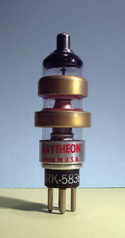
6BL6 (5836) – Sutton tube, a reflex klystron used as a 250mW CW microwave source, 1.6 to 6.5GHz depending upon an external cavity. 4-pin peewee base with cavity contact rings and top cap
6BL8, ECF80 – General-purpose Triode pentode used in TV, audio and test gear
6BM6 (5837) – Sutton tube used as a 150mW CW microwave source, 550MHz to 3.8GHz depending upon an external cavity. 4-pin peewee base with cavity contact rings and top cap
6BM8, ECL82 – Triode pentode used as the driver and output stages in audio amplifiers, audio output and vertical output stages in TV receivers and has even been seen in an electronic nerve stimulator.
6BN6 – Gated-beam discriminator pentode, used in radar, dual channel oscilloscopes and F.M. quadrature detectors (cf. 6DT6, nonode).
6BQ5, EL84,(N709) – 5.7Watts AF Power pentode, noval base
6BQ6-GT – Beam Power Pentode, used as a Horizontal Deflection Output tube in monochrome TV receivers of the 1950s. Most commonly used in receivers with diagonal screen sizes less than 19 inches (48cm). (However, may be found in some larger models.) Larger receivers often used similar type 6DQ6. Later versions of this tube branded as 6BQ6-GTB/6CU6.
6BQ7 – Dual RF/VHF triode with internal screen. The two sections can be used independently or in a cascode stage
6BQ7A – Improved 6BQ7 capable of operation at UHF frequencies
6BU8 – Split Anode TV Sync Separator
6BX6, EF80 – Sharp-cutoff RF/IF/Video pentode, noval base
6BY6 – Similar to type 6CS6, but with higher transconductance. 3BY6 with a different heater
6CW4 – Nuvistor high-mu VHF triode, most common one in consumer electronics
6CZ5 – Beam pentode for use in vertical deflection or audio amplifier. In certain applications, it can be used in place of a 6973.
6DA6, EF89 – R.F. Pentode used in AM/FM radios manufactured outside North America.
6DJ8, ECC88, E88CC, 6922, 6N23P, 6N11 – Dual Audio and R.F. Triode (often used in TV broadcast equipment, test gear, oscilloscopes and audiophile gear) similar to 6ES8
6DQ6 – Beam Power Pentode, used as a Horizontal Deflection Output tube in monochrome TV receivers of the 1950s. Most often found in receivers with diagonal screen measurements larger than 17 inches (43cm). Smaller receivers often used similar type 6BQ6-GT. Also used as Audio Output tubes in Standel guitar amplifiers. Later versions branded as 6DQ6-B/6GW6.
6DR8, EBF83 – R.F. pentode which will operate with 12V anode supply, used as I.F. amplifier in car radios which run directly off the 13.5 volt supply.
6DS4 – Nuvistor VHF triode used in TV tuners immediately prior to the introduction of solid state tuning circuits. (RCA TVs equipped with a 6DS4 tuner bore the trademark "Nu-Vista Vision"); successor of the 6CW4.
6DS8, ECH83 – Triode-heptode Local oscillator-Mixer which will operate with 12V anode supply, used in car radios which run directly off the 13.5 volt supply.
6DT6 – Quadrature detector used in TV audio circuits of the 1950s and early 1960s; cf. 6BN6, nonode.
6DV4 – Medium-mu Nuvistor triode for UHF oscillators; some versions had a gold-plated envelope
6DX8 – Triode pentode
6EM5 – TV Vertical Output Pentode
6ES6, EF98 – R.F. pentode which will operate with 12V anode supply, used as tuned R.F. amplifier in car radios which run directly off the 13.5 volt supply.
6ES8, ECC89, E89CC – Dual Triode used as cascode R.F. amplifier in TV tuners and V.H.F. receiver front ends, also used as general-purpose dual triode in test gear, similar to 6DJ8
6EZ8 – High-mu triple triode, Noval base
6FH8 – Medium-mu triode and three-anode sharp-cutoff tetrode for use in TV receivers and complex wave generators
6GK5 – Miniature V.H.F. triode (Used as V.H.F. local oscillator in some T.V. Turret Tuners)
6GM5 – Beam power pentode, identical to 7591 and 7868 with a Noval base
6GV8, ECL85 – Triode Pentode (TV vertical output)
6GW8, ECL86 – Audio Triode Pentode (audio, TV vertical output)
6GY8 – High-mu triple triode for use as oscillator, mixer, RF amplifier or AFC tube, Noval base
6HS8 – Dual-anode pentode for TV receiver sync separation service or as a two-channel VCA
6JU8A – 9mA, Quad diode, units 1&2 and 3&4 internally series-connected
6KM8 – Diode and three-anode sharp-cutoff tetrode for use in musical instruments, frequency dividers and complex wave generators
6LF6 – Beam power tetrode with a duodecar Compactron base and anode cap, for CRT horizontal-deflection amplifiers
6SB7Y (octal), 6BA7 and 12BA7 (Noval) – VHF pentagrids, 1946
6SC7 – High-mu dual triode (Both sections share a single cathode)
6SK7 – Remote-cutoff pentode (Used in I.F. stages of North American radios) Miniature version: 6BD6
6SL7, ECC35 – Dual triode (Used in TV and general electronics)
6SN7, ECC32, B65, 13D2, CV1986, 6042 – Medium-mu dual triode (Used in Audio Amplifiers, Hammond Organs and Television; extensive use in World War II radar) Each section is equivalent to a 6J5. Miniature version: 12AU7
6SS7 – Remote-cutoff pentode (150mA heater version of the 6SK7, found in some AA6 radios as both the RF amplifier and first IF). This is the only tube to have a same-letter repetition
"7" prefix Loctal tubes
These tubes all have 6.3 volt AC/DC heaters.
7A4 – Medium-mu triode, Loctal version of type 6J5, often numbered 7A4/XXL
7A5 – Beam power pentode, Loctal version of type 6U6GT
7A6 – Dual detector diode, similar to type 6H6
7A7 – Remote-cutoff pentode, Loctal version of type 6SK7
7C5 – Beam power pentode, Loctal version of type 6V6
7C6 – High-mu triode, dual detector diode
7C7 – Sharp-cutoff pentode
7E5 – Medium-mu high-frequency triode
7E6 – Medium-mu triode, dual detector diode, Loctal version of types 6R7 and 6SR7, electronically identical to miniature type 6BF6.
7E7 – Semiremote-cutoff pentode, dual detector diode, similar to types 6B7 and 6B8
7F7 – High-mu dual triode, Loctal version of type 6SL7-GT
7F8 – Medium-mu VHF triode, used as amplifier or converter
7G7 – Sharp-cutoff pentode
7G8 – Sharp-cutoff dual tetrode
7H7 – Semiremote-cutoff pentode
7J7 – Triode-heptode converter, similar to type 6J8-G
7K7 – High-mu triode, dual detector diode, similar to types 6AT6 and 6Q7
7L7 – Sharp-cutoff pentode
7N7 – Dual medium-mu triode, Loctal version of type 6SN7-GT
7Q7 – Pentagrid converter, similar to type 6SA7
7R7 – Remote-cutoff pentode, dual detector diode
7S7 – Triode-heptode converter
7T7 – Sharp-cutoff pentode
7V7 – Sharp-cutoff pentode; 7W7 but with the suppressor grid on pin 4, an internal shield on pin 5, and the cathode on pin 7
7W7 – Sharp-cutoff pentode; 7V7 but with the suppressor grid and internal shield on pin 5, and the cathode on pins 4 and 7Note: When substituting a 7V7 for a 7W7 or vice versa, verify connections on socket pins 4 and 7; pin 5 is usually connected to the chassis
7X6 – Dual rectifier diode
7X7 – High-mu triode, dual detector diodes on separate cathodes, used as FM discriminator and AF amplifier, often numbered 7X7/XXFM
7Y4 – Full-wave rectifier
7Z4 – Full-wave rectifier
7AB7 – Sharp-cutoff pentode
7AD7 – Power pentode
7AF7 – Dual medium-mu triode
7AG7 – Sharp-cutoff pentode
7AH7 – Remote-cutoff pentode
7AJ7 – Sharp-cutoff pentode
7AK7 – Sharp-cutoff, dual control pentode for computer service. Perhaps the first active device specifically designed for computer use.
12.6 volt heater tubes
12A5 – Power pentode. UX7 base. Center-tapped 12.6V/300mA resp. 6.3V/600mA heater. Mostly used in pre-war car radios.
12A7 – Power pentode, rectifier diode. Pentode section is similar to type 38. Diode has a low power rating – 120 volt, 30mA – that limits the number of tubes that can be tied to its B+ circuit. Used in one-tube portable phonographs and a few two- and three-tube radios. Forerunner of such types as 32L7-GT, 70L7-GT and 117L7-GT. UX7 base with top cap. Not related to types 2A7 and 6A7.
12AE10 – Compactron Beam power tube and sharp-cutoff pentode
12AL5 – Dual diode (similar to 6AL5 except for heater)
12AT6 – Dual diode/triode (Commonly replaced by 12AV6 in consumer radios)
12AT7, ECC81, 6060, B309, M8162 – High-mu dual triode. Commonly used as R.F. amplifier/mixer in VHF circuits.
12AU7, ECC82, 6067, B329, M8136 – Medium-mu dual triode. Two 6C4/EC90s in one envelope;[34] however, it is only specified as an audio frequency device. Commonly used in audio applications and TV receivers.
12AV6 – Dual diode/High-mu triode (see also: 6AV6)
12AV7, 5965 – Medium-mu dual triode. Principally designed for VHF amplifier/mixer operation.[35]
12AX7, ECC83, 6057, B327, M8137 – High-mu dual triode. Very similar to triode section of 6AV6. Commonly used in high-gain audio stages and as power inverters in class A/B amplifiers.
12AW7 – See 12DW7 below. Called AW by some, but proper name is DW.
12AY7 – Dual Triode. Medium gain but low noise, intended for low-level/preamplifier use.
12AZ7 – Dual Triode. Medium-mu, AF Amplifier, or combined oscillator and mixer, Noval base.[36]
12BA6 – Remote-cutoff pentode, 6BA6/EF93 with a different heater
50X6 – Dual Diode (Loctal, commonly used as a rectifier-doubler)
50DC4 – Rectifier diode (Similar to 35W4 except for heater)
50EH5 – Beam Power tube, (Similar to 50C5 but with higher gain, some radios that use this tube do not have an audio amplifier section.)
50HK6 – Power pentode (Filament is tapped for use with a dial lamp)
117 volt heater tubes
All of the following tubes are designed to operate with their heaters connected directly to the 117 volt (now 120 volt) electrical mains of North America. All of them use indirectly heated cathodes. All of them incorporate at least one rectifier diode.
Rectifier diode – Beam power pentode combinations
117L7GT
117M7GT
117N7GT
117P7GT
Rectifier tubes
117Z3 – Single diode, 7-pin miniature version of 117Z4GT
117Z4GT
117Z6GT – Dual diode, can be used as a voltage doubler
Other tubes with nonstandard heater voltages
The tubes in this list are most commonly used in series-wired circuits.
5J6 – General purpose RF dual triode with common cathodes, a 6J6 with a 4.7volt/600mA controlled warm-up heater[39]
8B10 – Compactron Dual triode and dual diode
2AF4 – UHF triode oscillator
2BN4 – VHF triode
2CW4 – Nuvistor high-mu VHF triode, 6CW4 with a 2.1volt/450mA heater; used in TV receivers with series heater strings
2H21 – Phasitron, a magnetically controlled beam-deflection phase modulator tube[41] similar to the 5593, used in early FM broadcast transmitters[42][43][44]
6C21 – Triode radar modulator for "hard tube" pulsers.
7C23 – 120kW Power triode for high voltage pulse operation.
8D21 – Internally water cooled dual tetrode used in early VHF TV transmitters.
9C21 – 100kW Water-cooled power triode, directly heated, 4-pin base with dual top caps for grid and anode
List of EIA professional tubes
Note: Most of these are special quality versions of the equivalents given. Some manufacturers preceded the EIA number with a manufacturer's code, as explained above.
5000s
5651
5331, 5332, 5514 – Directly heated power triodes, 4-pin base with anode top cap
5556 – Directly heated power triode, 4-pin base
5593 – Phasitron, a magnetically controlled beam-deflection phase modulator tube[46] similar to the 2H21, used in early FM broadcast transmitters[42][43][44]
5608 – Dual power triode, designed for use with AC anode voltage and critical grid leak requirements
5651 – 86-volts, cold-cathode, glow-discharge voltage reference, 7-pin miniature base
5654, CV4010, 408A – VHF pentode; common in vintage radar IF amplifiers; premium version of 6AK5, EF95, 6J1P (6Ж1П)
5729 – Beam-deflection, 30-channel analog multiplexer for telecomms transmitting channel banks, internal electrostatic focusing and deflection to determine through which one out of 30 grids the electron beam passes to the common anode.[47] Cf. 5738, 6090, 6091, 6170, 6324
5731 – Narrow-tolerance selected 955Acorn triode for use in Radiosonde weather balloon transmitters
5734 – Mechano-electronic displacement sensor; a vacuum triode with its anode mounted on a shaft that extends through a thin, flexible metal diaphragm; shaft movement is reflected in anode current; Fres = 12kHz[48][49]
5738 – Beam-deflection, secondary emission, 25-channel analog multiplexer, internal electrostatic focusing and deflection to determine which one out of 25 individually controllable dynodes receives the electron beam controlled by a common grid.[50] Cf. 5729, 6090, 6091, 6170, 6324
5749– RF pentode; premium version of 6BA6, EF93, W727
5750 – Heptode mixer; premium version of 6BE6, EK90, X727
5751 – Low-noise avionics dual triode with separate cathodes
5814A – Industrial, computer-rated version of 12AU7/ECC82
5836, 6BL6Raytheon RK5836 – Sutton tube, a reflex klystron used as a 250mW CW microwave source, 1.6 to 6.5GHz depending upon an external cavity. 4-pin peewee base with cavity contact rings and top cap
5837, 6BM6 – Sutton tube used as a 150mW CW microwave source, 550MHz to 3.8GHz depending upon an external cavity. 4-pin peewee base with cavity contact rings and top cap
5845 – Dual directly heated saturated-emission diode. Acts as a heating current-controlled, variable series resistor in voltage/current stabilizer circuits.
5876A – Glass pencil-type disk-seal UHF power triode up to 2GHz
5963, 5964, 5965 – Dual triode, designed for high speed digital computers, has a high zero-bias anode current, industrial/computer-rated versions of 12AV7
5998, 6336A, 6394, 6520, 6528, 7802 – Dual power triodes, designed for series voltage regulator applications
6000s
6047 – Additron, a triple-control grid, split-anode tetrode for use as a single-bit digital full adder[51] (technically a hexode)
6057, M8137 – High-mu dual triode; premium version of 12AX7, ECC83, B339
6059 – Low-microphonics pentode; premium version of 6BR7
6060, M8162 – High-mu dual triode; premium version of 12AT7, ECC81, B309
6064, M8083 – R.F. pentode; premium version of 6AM6, EF91, Z77
6067, M8136 – Medium-mu dual triode; premium version of 12AU7, ECC82, B329
6080 – Very-low impedance dual power triode, designed for series voltage regulator applications, now popular for output transformerless audio amplifiers; premium version of 6AS7
6082 – Ruggedized, indirectly heated power triode, octal base
6090 – Beam-deflection, 18-channel analog demultiplexer for telecomms receiving channel banks, internal electrostatic focusing and deflection to determine which one out of 18 anodes receives the electron beam controlled by a common grid.[52] Cf. 5729, 5738, 6091, 6170, 6324
6091 – Beam-deflection, 25-channel analog multiplexer for telecomms transmitting channel banks, internal electrostatic focusing and deflection to determine through which one out of 25 grids the electron beam passes to the common anode.[53] Cf. 5729, 5738, 6090, 6170, 6324
6146 – 60MHz, 120W AF/RF/VHF beam power pentode
6146B (8298A) – Improved version of 6146, 6146A and 8298.
6170 and 6324 – Beam-deflection, 25-channel analog multiplexer for telecomms transmitting channel banks, external focusing and deflection by a multiphase, rotating magnetic field to determine through which one out of 25 grids the electron beam passes to the common anode.[54] Cf. 5729, 5738, 6090, 6091
6173 – Pencil-type disk-seal UHF diode up to 3.3GHz
6196 – Directly heated dual, compensating electrometer tetrode with space charge grids for use in the 2 branches of a differential-in, differential-out bridge circuit[55]
6218/E80T (CV5724) – Modulated, single-anode beam deflection tube for pulse generation up to 375MHz; shock resistant up to 500g[56][57]
6263 – Pencil-type disk-seal UHF power triode up to 500MHz, Panode = 8W
6351 – Secondary emission pentode for wide band RF amplifiers
6361 – Convectron, an inclinometer tube that senses tilt from the vertical by means of different gas convections around a heating wire in a glass envelope, of two 6361s aligned in a 90° V-shaped position to each other and the heating wires connected in a bridge circuit
6441 – 650V, 100mAavg, 300mAsurgeTacitron, a grid turn-off hydrogen thyratron with a grid that forms a shield around both the cathode and anode and separates the two by a wire mesh, so the arc discharge can be extinguished by a negative grid that surrounds the positive anode with a field of opposing polarity and inhibits conduction, taking over part of the anode current during deionisation – similar to today's GTOs; Octal base[58]
6462 – Magnetic pickup tube, a 1-axis beam-deflectionmagnetometer with approx. 1G (100μT) resolution; an electron beam is electrostatically centered between two anodes while no magnetic field is present; the magnetic field to be detected will then deflect the beam more towards one of the anodes, resulting in an imbalance between the two anode currents[59]
6762 – Wamoscope, a TWT/CRT combination used to directly visualize an incoming microwave signal by electron velocity-sorting[64]
6835, 7570, 7571 – Single-electron gunrecording storage tube, an analog videoframe freezer tube. This was achieved by a CRT that writes the video image onto a thin, dielectric target and subsequently can read the generated charge pattern up to 30000 times from that target, producing a video signal containing a static shot that resembles a still photograph[65][66][67]
6877, 7233 – Power triodes, designed for series voltage regulator applications
6900 – Dual power triode for pulse applications in missiles, avionics and industrial systems; noval base
6922 (E88CC, industrial version of 6DJ8/ECC88)
6973 – Power pentode similar in shape, size, and base to the EL84/6BQ5, but with a high gain for more than double the output range. Popular in some makes of 1960s era guitar amplifiers, though rarely implemented in modern times.
7000s
7025 – Low-hum, noise and microphonics version of 12AX7
7027 – AF Power pentode, improved 6L6 with a 25 Watt anode and different pinout
7199 – Triode-pentode, noval base. Similar to 6U8.
7229,[69]7230,[70]7231,[71]7232,[72]7439, 7440, 7441, 7595, 7596, 7597, 7598, 7599, 7600, 7602 – Krytrons, cold-cathode gas-filled trigger tubes with a primer electrode for use as a very high-speed, high-surge current switch[73]– second source to EG&G
7236 – Dual power triode for use as long-life power amplifier in computer applications
7241, 7242 – Triple-cathode power triodes, designed for hi-rel cathode follower series voltage regulator applications where the cathode is split into 3 sections connected together via balancing resistors to equalize the emission along the cathode
7414 – Time Totalizer, a metal-vapor coulometer, a cold-cathode gas-discharge tube where metal is constantly sputtered off the cathode and deposited on a collector element whose resistance therefore decreases with elapsed time[77]
7430 – Flat-envelope version of the 6AK5/EF95 sharp-cutoff pentode for use on PCBs in Radiosonde weather balloon transmitters
7548 – Secondary emission hexode for pulse generator and pulse amplifier applications
7551 – Noval-base beam power pentode with 12-15 volt heater. 6.3 volt heater version was 7558. Used in telephony, RF amplification, and more rarely AF amplification.
7554 – Ceramic/metal pencil-type disk-seal SHF power triode up to 5GHz
7572, 7575, 7702 – Dual-electron gunrecording storage tube, a realtime analog videoframe freezer tube with simultaneous R/W, and storing capability. This was achieved by a CRT/camera tube combination; the CRT part writes the video signal onto a thin, dielectric target, which can hold the generated charge pattern for many hours; the camera part reads the charge pattern from the back side of this target, producing a video signal containing a static shot that resembles a still photograph[78][79][80]
7586 – First Nuvistor available on the market, medium-mu triode
7587 – Nuvistor Sharp cutoff tetrode
7591 – Beam power pentode, octal base. Found in many guitar amps made by Gibson and Ampeg.
7763 – Beam deflection tube, used as IF amplifier/limiter where a constant phase shift over a wide range of input signal amplitudes is required[81]
7768 – Miniature ceramic/metal disk-seal planar SHF triode up to 4GHz
7868 – Beam power pentode, B9E Novar base version of 7591. Found in many of the once popular Challenger series PA amps made by Bogen Communications, also found in some guitar amplifiers made by Ampeg.
8514 – 1kV/10...800μA Corona voltage reference, 7-pin with anode top cap
8515 – 1.6kV/20...950μA Corona voltage reference, 7-pin with anode top cap
8526 – Nuvistor-type medium-mu dual triode
8873 – 500MHz, 200W anode dissipation power triode
8874 – 500MHz, 400W anode dissipation power triode
8875 – 500MHz, 300W anode dissipation power triode
8877 = 3CX1500A7 – Ceramic, forced air cooled, 1.5kW power triode
8974 (X-2159) – Giant water-cooled megawatt-class tetrode used for very high-power broadcast and industrial service; possibly the most powerful tube ever commercially produced
XP1010 – 10-stage photomultiplier for r-ray and gamma ray scintillation spectrometry, selected 150AVP for low noise and resolution, blue-sensitive Sb-Cs cathode, Ag-Mg-O-Cs dynodes, duodecal (12-pin) base
XP1011 – 10-stage photomultiplier, blue-sensitive Sb-Cs cathode, Ag-Mg-O-Cs dynodes, shock and vibration-proof, duodecal base
XP1120 – 17-stage photomultiplier for x-ray (λ > 200pm) or UV (λ < 150nm) photon counting in a high-vacuum environment, Nickel cathode, Cu-Be-O dynodes, coaxial outputs, built-in resistor ladder
XP1121 – 17-stage photomultiplier for ion (> 10keV) or electron (0.1...10keV) photon counting in a high-vacuum environment, Cu-Be-O cathode and dynodes, coaxial outputs, built-in resistor ladder
XP1122 – 17-stage photomultiplier for x-ray (λ > 200pm) or UV (λ < 150nm) photon counting in a high-vacuum environment, Nickel cathode, Cu-Be-O dynodes, coaxial outputs, built-in resistor ladder
XP1123 – 17-stage photomultiplier for ion (> 10keV) or electron (0.1...10keV) photon counting in a high-vacuum environment, Cu-Be-O cathode and dynodes, coaxial outputs, built-in resistor ladder
XP1130 – 17-stage photomultiplier for x-ray (λ > 200pm) or UV (λ < 150nm) photon counting in a high-vacuum environment, Nickel cathode, Cu-Be-O dynodes, coaxial outputs, built-in resistor ladder
XP1131 – 17-stage photomultiplier for ion (> 10keV) or electron (0.1...10keV) photon counting in a high-vacuum environment, Cu-Be-O cathode and dynodes, coaxial outputs, built-in resistor ladder
XX1190 – 1. Gen. inverter, 1-stage image intensifier
XX1192 – 1. Gen. inverter, 1-stage image intensifier
XX1200 – 1. Gen. inverter, 1-stage image intensifier
XX1211 – 1. Gen. inverter, 3-stage image intensifier
XX1270 – 1. Gen. inverter, 2-stage image intensifier
XX1400 – 2. Gen. inverter, 1-stage image intensifier
XX1430 – 1. Gen. inverter, 1-stage image intensifier
XX1510 – 1. Gen. 3-stage image intensifier
XX1610 – 2. Gen. image intensifier
XX1800 – 2. Gen. proximity focused, 1-stage image intensifier
Y - Vacuum tubes
YA
YA1000 – 5kV, 5mA, Directly heated saturated-emission diode with pure-metal cathode for use in RMS converters of AC voltage/current stabilizer circuits, noval base[83]
YD
YD1000 – 45kW, Water-cooled RF power triode
YD1001 – 35kW, Air-cooled RF power triode
YD1012 – 180kW, Vapor-cooled RF power triode
YD1130 – 400W, Air-cooled, linear RF/AF power triode
YD1252 (RS 2051 V) – 180kW, Water-cooled, modulator power triode
YD1300 – 300W, Air-cooled, UHF power triode
YD1301 – 300W, Air-cooled, UHF power triode
YD1302 – 300W, Air-cooled, UHF power triode
YD1332 – 1.8kW, Air-cooled, UHF power triode
YD1333 – 900W, Air-cooled, UHF power triode
YD1334 – 1.8kW, Air-cooled, UHF power triode
YD1335 – 1.9kW, Air-cooled, UHF power triode
YD1336 – 1.8kW, Air-cooled, UHF power triode
YD1342 – 30MHz, 240kW, Water-cooled RF power triode
YD1352S (8867, DX334) – 5MHz, 2kW, Water-cooled Neotron, a gridless field-effect tube where a magnetically focused electron beam is modulated by varying the voltage of a gate electrode surrounding it. Used as RF power amplifier or oscillator
YG
YG1000 – Directly heated electrometer tetrode with an oxide cathode and a space charge grid, grid current ≤600fA, magnoval base with input grid on top cap
ZA1001 – Neon-filled, coaxial, tritium-primed, sputtered-molybdenum cold-cathode switching diode with traces of heavy gas (krypton/xenon) for slow de-ionization, e.g. for low-frequency relaxation oscillators; meshed cylinder anode, all-glass wire-ended
ZA1002 – Neon-filled, coaxial, tritium-primed, sputtered-molybdenum cold-cathode switching diode, large difference between burning and ignition voltage, meshed cylinder anode, 3-pin all-glass wire-ended
ZA1003 – Neon-filled, coaxial, tritium-primed, sputtered-molybdenum cold-cathode switching diode for use as indicator tube in transistorized circuits, meshed cylinder anode, 3-pin all-glass wire-ended
ZA1004 – Neon-filled, coaxial, tritium-primed, sputtered-molybdenum cold-cathode switching diode, small difference between burning and ignition voltage, for use as indicator tube in transistorized circuits or as 86.4V Voltage reference, meshed cylinder anode, 3-pin all-glass wire-ended
ZA1005 – Neon-filled, coaxial, tritium-primed, sputtered-molybdenum cold-cathode switching diode for use like a DIAC in thyristor circuits, meshed cylinder anode, 2-pin all-glass wire-ended
ZC
ZC1010 (Z661W) – 8mAavg, 50mApeak, Gas-filled, cold-cathode AC trigger pentode, two starters and a primer electrode, positive starter voltage, 5-pin all-glass wire-ended, envelope inside radioactively coated for a constant ignition voltage, for use in bidirectional counters
ZC1040 – 25mA, Gas-filled, cold-cathode AC trigger tetrode, one starter and a primer electrode, positive starter voltage, noval base
ZC1050 – 2mA, Gas-filled, cold-cathode, luminescent trigger tetrode, one starter and a primer, 300mlm light output[85] for use as self-displaying shift register cells in large-format, crawling-text dot-matrix displays;[86] all-glass wire-ended
ZC1060 – 20mAavg, 5kApeak, Gas-filled, cold-cathode, high-current trigger triode for e.g. capacitor discharge circuits. One external (capacitive) starter electrode
ZM1020 (Z520M) – ZM1022 with a red contrast filter coating
ZM1021 (Z521M) – ZM1023 with a red contrast filter coating, for use with ZM1020
ZM1022 – 0 1 2 3 4 5 6 7 8 9 Neon-filled digital indicator tube, 15.5mmCH top-viewing, no decimal point
ZM1023 – A V Ω% + - ~ Neon-filled digital indicator tube, 15.5mmCH top-viewing, for use with ZM1022 in digital multimeters
ZM1024 – ZM1025 with a red contrast filter coating, for use with ZM1020
ZM1025 – c/s Kc/s Mc/s μs ms ns s Neon-filled digital indicator tube, 15.5mmCH top-viewing, for use with ZM1022 in digital frequency counters
ZM1030 – ZM1032 with a red contrast filter coating
ZM1031 – ZM1031/01 without the ~
ZM1031/01 – ZM1033/01 with a red contrast filter coating, for use with ZM1030
ZM1032 – 0 1 2 3 4 5 6 7 8 9 Neon-filled digital indicator tube, 15.5mmCH side-viewing, no decimal point, 5 dual cathodes and separate odd/even anode compartments for biquinary multiplexing
ZM1033/01 – + - ~ Neon-filled digital indicator tube, 15.5mmCH side-viewing, separate anode compartment for +, for use with ZM1032
ZM1040 (Z522M) – ZM1042 with a red contrast filter coating
ZM1041 – ZM1043 with a red contrast filter coating, for use with ZM1040
ZM1041S – ZM1043S with a red contrast filter coating, for use with ZM1040
ZM1042 (Z5220M) – 0 1 2 3 4 5 6 7 8 9 Neon-filled digital indicator tube, 30mmCH side-viewing, no decimal point
ZM1043 – + - Neon-filled digital indicator tube, 30mmCH side-viewing, for use with ZM1042
ZM1043S – Y X + W U Z - Neon-filled digital indicator tube, 30mmCH side-viewing, for use with ZM1042
ZM1047 – ZM1049 with a red contrast filter coating, for use with ZM1040
ZM1049 – T F S N Z Y G H M X Neon-filled digital indicator tube, side-viewing, for use with ZM1042 in numerical control systems
ZM1050ZM1070 (Z550M, 8453) – Neon-filled digital indicator tube, top-viewing, dekatron-type readout with common anode and common cathodes, pulsating anode voltage, controlled by 5-volts sensitive starter electrodes, for transistorized circuits
ZM1130 – ZM1132 with a red contrast filter coating
ZM1131 – ZM1133 with a red contrast filter coating, for use with ZM1080
ZM1132 – 0 1 2 3 4 5 6 7 8 9 Neon-filled digital indicator tube, side-viewing, left and right decimal point
ZM1133 – + - ~ Neon-filled digital indicator tube, side-viewing, for use with ZM1132
ZM1136L/R – ZM1138L/R with a red contrast filter coating
ZM1137 – ZM1139 with a red contrast filter coating, for use with ZM1136L/R
ZM1138L/R – 0 1 2 3 4 5 6 7 8 9 Neon-filled digital indicator tube, 13mmCH side-viewing, left or right decimal points (specify)
ZM1139 – + - ~ Ω Neon-filled digital indicator tube, 13mmCH side-viewing, for use with ZM1138 in digital multimeters
ZM1162 – 0 1 2 3 4 5 6 7 8 9 Long-life neon-filled digital indicator tube, 15.5mmCH top-viewing, no decimal point, rectangular envelope for close stacking in both axes
ZM1170 – ZM1172 with a red contrast filter coating
ZM1172 – 0 1 2 3 4 5 6 7 8 9 Neon-filled digital indicator tube, 15.5mmCH side-viewing, no decimal point
ZM1174 – ZM1175 with a red contrast filter coating
ZM1175 – 0 1 2 3 4 5 6 7 8 9 Neon-filled digital indicator tube, 15.5mmCH side-viewing, left decimal point
ZM1176 – ZM1177 with a red contrast filter coating
ZM1177 – ZM1175, but right decimal point
ZM1180 – ZM1182 with a red contrast filter coating
ZM1181 – ZM1183 with a red contrast filter coating, for use with ZM1180
ZM1182 – 0 1 2 3 4 5 6 7 8 9 Neon-filled digital indicator tube, 16mmCH top-viewing, no decimal point, semi-rectangular envelope for close horizontal stacking
ZM1183 – + - ~ Ω Neon-filled digital indicator tube, top-viewing, 13mmCH for use with ZM1182 in digital multimeters
ZM1184D – ZM1185D with a red contrast filter coating
ZM1185A (GR1420) – 1 2 3 4 5 6 U K E R Neon-filled digital indicator tube, 16mmCH top-viewing
ZM1185D (GR1430) – ∇ Δ Neon-filled digital indicator tube, 16mmCH top-viewing, for use in elevators
ZM1185E (GR1472) – 0 1 2 3 4 5 - t kg + Neon-filled digital indicator tube, 16mmCH top-viewing
ZM1200 – Pandicon, multiplexed 14-digit display tube with decimal points and punctuation marks, pin connections on both ends
ZM1202 – 12-Digit Pandicon
ZM1204 – 10-Digit Pandicon
ZM1206 – 8-Digit Pandicon
ZM1210ZM1212 – ZM1212 with a red contrast filter coating
ZM1212 – 0 1 2 3 4 5 6 7 8 9 Neon-filled digital indicator tube, 15.5mmCH side-viewing, left decimal point, all-glass wire-ended
ZM1220 – ZM1222 with a red contrast filter coating
ZM1222 – 0 1 2 3 4 5 6 7 8 9 Large neon-filled digital indicator tube, 40mmCH side-viewing
ZM1230 – ZM1232 with a red contrast filter coating
ZM1232 – 0 1 2 3 4 5 6 7 8 9 Neon-filled digital indicator tube, 15.5mmCH upside-down side-viewing, no decimal point
ZM1240 – ZM1242 with a red contrast filter coating
ZM1241 – ZM1243 with a red contrast filter coating, for use with ZM1240
ZM1242 – 0 1 2 3 4 5 6 7 8 9 Neon-filled digital indicator tube, 16mmCH side-viewing, right decimal point
ZM1243 – + - ~ Ω Neon-filled digital indicator tube, 16mmCH side-viewing, for use with ZM1242 in digital multimeters
ZM1330 – ZM1332 with a red contrast filter coating
ZM1331 – ZM1333 with a red contrast filter coating, for use with ZM1330
ZM1332 – 0 1 2 3 4 5 6 7 8 9 Neon-filled digital indicator tube, 13.1mmCH side-viewing, left and right decimal points, all-glass wire-ended
ZM1333 – + - ~ Ω Neon-filled digital indicator tube, 13.1mmCH side-viewing, all-glass wire-ended, for use with ZM1332 in digital multimeters
ZM1334 – ZM1336 with a red contrast filter coating
ZM1335 – ZM1337 with a red contrast filter coating, for use with ZM1334
ZM1336 – 0 1 2 3 4 5 6 7 8 9 Neon-filled digital indicator tube, 13.1mmCH side-viewing, left and right decimal points, multiplex-capable
ZM1337 – + - ~ Ω Neon-filled digital indicator tube, 13.0mmCH side-viewing, right decimal point (!), all-glass wire-ended, red contrast filter coating, for use with ZM1336 in digital multimeters
ZP1600 – Halogen-quenched Geiger-Müller tube, 19.8mm diameter mica window, X-rays, 6.0 to 20keV energy, 60 to 200pm wavelength range
ZP1610 – Side window, organically quenched Geiger-Müller tube. 7 x 18mm mica window; X-rays, 2.5 to 40keV energy, 30 to 500pm wavelength range
ZP1700 – Halogen-quenched, cosmic-ray guard counter tube for low-background measurements; to be used with another radiation counter tube in an anticoincidence circuit
ZP1800 – Halogen-quenched Geiger-Müller tube for use at temperatures up to 200°C, γ
ZP1810 – Halogen-quenched Geiger-Müller tube for use at temperatures up to 200°C, γ, low sensitivity, up to 40 mGy/h
ZP1860 – Halogen-quenched Geiger-Müller tube, β and γ
QE05/40 (6146) – 40W Radiation-cooled output beam-tetrode, popular amongst radio amateurs as a final RF amplifier
QE08/200 – 200W Beam-tetrode
QEL
QEL1/150 – Air-cooled 150W beam-tetrode
QEL1/250 – Air-cooled 250W beam-tetrode
QEP
QEP20/18 – 18W Beam-tetrode for use as a pulse modulator
QQC
QQC03/14 – 14W Dual beam-tetrode
QQE
QQE02/5 (6939) – 5W Dual beam-tetrode
QQE03/12 (6360) – 12W Dual beam-tetrode
QQE03/20 (6252) – 20W Dual beam-tetrode
QQE04/5 (7377) – 5W Dual beam-tetrode
QQE06/40 (5894, YL1060) – 40W dual beam-tetrode, internally neutralized, Septar base with dual anode top cap
QQV
QQV02/6 – 6W dual beam-tetrode
QQV03/20A – 20W Radiation-cooled split-anode tetrode made by Mullard and used in the 1940s, 1950s and 1960s as a VHF frequency-doubling output stage with balanced output.
QQV07/50 – 50W Dual beam-tetrode
QQZ
QQZ03/20 (8118, YL1020) – 20W Dual beam-tetrode
QQZ06/40 (YL1030) – 40W Dual beam-tetrode
QV
QV04/7 – 7W Beam-tetrode
QV05/25 (807) – 25W Radiation-cooled output beam-tetrode made by Mullard.
QV2/250C – 250W Beam-tetrode
QY
QY3/65 – 65W Beam-tetrode
QY5/3000A – 3kW Beam-tetrode
QY5/3000W – Water-cooled version of QY5-3000A
QYS
QYS50/P40 – Pulsed power tetrode, Silica envelope, 50kV anode voltage, considerable x-radiation, 810°C anode temperature at 700W anode dissipation, 40A anode current at duty factor 0.0005, Vg1Cut-off(IA=1mA@VA=55kV):>-3.4kV, gm:38mS
TYS5/3000 – Power triode, Silica envelope, 6kV anode voltage, 950°C anode temperature at 3.5kW anode dissipation, 2.8A cathode current, gm:15mS. Used in RF generators for induction hardening.
X - Thyratron
XGQ
XGQ2/6400 – 2kV, 6.4A Mercury-vapor tetrode thyratron with anode and grid1 top caps
XR
XR1/1600 (5545) – 1kV, 1.6A Inert gas-filled triode thyratron with anode top cap
XR1/6400 – 1kV, 6.4A Inert gas-filled triode thyratron with anode top cap
Compagnie des Lampes (1921, "French Mazda") and Mazda-Belvu
Not to be confused with Compagnie des Lampes (1888, see above) nor with British Mazda (see above).
IN-33 ИН-33 – Neon-filled, planar, dual 105-segment linear glow-transfer plasma bar graph display with three cathode strings, for use in VU meters etc.; similar to BG16101
•
•
•
•
•
•
•
•
•
•
•
•
•
•
•
•
ITM2-M ИТМ2-М – Four-color phosphored-thyratronlatchingpixel; 4x4 array of 4 subminiature dual-starter luminescent thyratrons each for the colors red, yellow, green and blue (thus, 5 intensities per color yields 54 = 625 colors), 4x4 matrix of 10-volts sensitive starter electrodes, cubic envelope for easy stacking in both axes, 12-pin all-glass wire-ended,[95] similar to today's RGBA LEDs
ITS1 ИТС1 – Green phosphored-thyratron latching seven-segment display, no decimal point, 5-volts sensitive starter electrodes, all-glass wire-ended, rectangular envelope for easy stacking in both axes
MTX-90 МТХ-90 – Small neon-filled thyratron for use as a latching single-dot indicator, top-viewing, top of envelope acts as a magnifier, all-glass wire-ended, comes with a blob of solder on the end of each wire for rapid installing, like today's ball grid arrays
1602 – Directly heated power triode used for A.F. amplification with low microphonics. 7.5 volt filament. 12 watts of A.F. operating in Class-A. 15 watts of low R.F. operating in Class-C. Similar to type 10.
1603 – Indirectly heated pentode used for A.F. amplification with low microphonics. Similar to types 6U7, 57, 6D6 and 6C6. UX6 Base.
1608 – Directly heated triode giving 20 watts at up to 45MHz. 2.5 volt heater/filament. UX base.
1609 – Directly heated pentode used for A.F. amplification with low microphonics. American 5-Pin(UY)base.
1610 – Directly heated pentode specially designed for use as a crystal oscillator. 2.5 volt heater/filament, American 5-Pin base.
1612 – Pentagrid converter; low-microphonics version of type 6L7. Both control grids (1 and 3) are sharp-cutoff.
1619 – Beam Power Tetrode, similar to 6L6 with directly heated filament, common in World War II battle tank transmitters.
1624, 1625 – Very similar to the 807, but with different heater voltage
1626 – RF triode, very similar to 6J5 but with 12.6 volt filament
29C1 – Directly heated saturated-emission diode; acts as a heating current-controlled, variable series resistor in voltage/current stabilizer circuits.
200s
203A – 100W, Directly heated RF transmitter power triode, 4-pin base, anode on top cap
204A – 250W, Directly heated RF transmitter power triode, 3-pin base, anode on top cap
205D – 14W, Directly heated AF or modulator power triode, 4-pin base
207 – 10kW, Water-cooled, directly heated RF transmitter power triode
210T – Directly heated RF transmitter power triode, 4-pin base, similar to type 10 triode with an isolantite base
210DET – Cossor directly heated, 2 volts, special detector
4598, 7539, 7828, 8087, 8098 – Graphechon dual-electron gun scan conversion tubes, analog video transcoders with simultaneous R/W capability for realtime resolution and frame rate transcoding between different analog video standards. This was achieved by a CRT/camera tube combination; the CRT part writes onto a thin, dielectric target; the camera part reads the generated charge pattern at a different scan rate from the back side of this target.[102][103][104][105][106] The setup could also be used as a genlock
4205E = 205E – Directly heated power triode, 4-pin bayonet base with offset pin
4270A = 270A = 3C/350E – Directly heated power triode, 3-pin base
4275A = 275A – Directly heated power triode, 4-pin base
4300A = 300A – Directly heated power triode, 4-pin base
4307A = 307A – Power pentode similar to the output beam-tetrode type 807. It differs from an 807 by being a directly heated pentode rather than an indirectly heated beam-tetrode. Both types are contained in an ST-16 bulb with an anode cap and 5-pin "American" UY base
The SY4307A is historically notable because a pair of them in parallel Class-C was used as the output stage in a transmitter built in secret by Australian soldiers in Japanese-occupied Portuguese Timor during World War II in 1942. This transmitter, now reconstructed and on display at the Australian War Memorial in Canberra, was called "Winnie the War Winner".[107]
7JP4 – Monochrome cathode ray tube common in early postwar TV receivers. Electrostatic deflection, P4 white, medium-persistence phosphor, 7-inch (180mm) screen.
7JP7 – Monochrome cathode ray tube for use in early postwar radar displays. Electrostatic deflection, P7 blue-white, long-persistence phosphor, 5+1⁄2-inch (140mm) screen.
700s
703A – Directly heated Doorknob UHF power triode up to 1.5GHz
713A – Indirectly heated Little Doorknob UHF pentode, Bakelite Octal base
800 – Directly heated V.H.F. power triode, giving 35watts up to 60MHz and 18watts at 180MHz. American 4-Pin(UX)base with side locating pin.
801 – Directly heated power triode, used in pairs in Class-B in A.M. modulation sections of transmitters giving up to 45 watts of power at 60MHz and 22 watts at 120MHz.
802 – Indirectly heated H.F. power pentode, giving 8 watts up to 30MHz and 4 watts at 110MHz.
803 – Directly heated H.F. power pentode, giving 50 watts up to 20MHz and 25 watts at 70MHz.
804 – Directly heated H.F. power pentode, giving 20 watts up to 15MHz and 10 watts at 10MHz.
805 – Directly heated H.F. high-mu triode, giving 140 watts up to 30MHz and 70 watts at 85MHz.
806 – Directly heated H.F. high-mu triode, giving 390 watts up to 30MHz 195 watts at 100MHz.
807 – Indirectly heated H.F. beam power tetrode, giving 25 watts up to 30MHz and 12 watts at 125MHz. A variation of type 6L6 originally designed as a Class-C transmitter tube. Later used in pairs as push-pull outputs for high-wattage Class-AB2 audio amplifiers. Also used as a horizontal output tube in early TV receivers. One of the first commercial tubes that used the top cap to connect the anode (instead of the control grid) to the circuit.
808 – Directly heated H.F. high-mu triode, giving 140 watts up to 30MHz and 70 watts at 130MHz.
809 – Directly heated H.F. high-mu triode, giving 55 watts up to 27MHz and 30 watts at 100MHz.
810 – Directly heated H.F. triode, 10 volt filament and Zirconium Carbide anode. Base fits R.C.A. UT-541A Socket.
813 – Beam Power Tetrode possessing about 5 times the Anode dissipation of an 807.
814 – A directly heated Beam Power Tetrode giving about 130 watts at 30MHz and 65 watts at 100MHz operating in Class-C.
815 – An indirectly heated dual beam power pentode. Octal base.
825 – First commercially available klystrode, a VHF/UHF linear-beam transmitting tube, similar to a klystron
829 – A dual indirectly heated beam power tetrode. Two 6.3 volt heaters sharing a common tap.
830 – A directly heated triode giving about 50 watts at 15MHz and 7.5 watts at 60MHz operating in Class-C.
831 – A directly heated triode giving about 400 watts at 20MHz and 200 watts at 60MHz operating in Class-C. 11 volt heater/filament.
833 – A larger directly heated high-mu triode giving about 1kW at 30MHz and 500 watts at 45MHz operating in Class-C. Usable up to 100MHz at reduced power, (400W). 10volt heater/filament drawing 10A. The anode of this device is fabricated from tantalum. Anode current of 800mA with an anode voltage of 3kV and grid voltage of zero. Anode current of 4.3A at a voltage of 750 with 350 volt on the grid. Uses two-part R.C.A socket assembly UT-103.[109]
834 – A directly heated triode giving 58 watts at 100MHz and 25 watts at 350MHz operating in Class-C. 7.5 volt heater/filament. Fitted with an American 4-Pin, (UX4), base with side locating pin.
836 – An indirectly heated high vacuum rectifier with a peak inverse voltage of 5kV and peak anode current of 1 ampere. 2.5 volt heater.
837 – An indirectly heated pentode giving 11 watts at 20MHz and 5 watts at 80MHz. operating in Class-C. 12.6 volt heater.
838 – A directly heated triode giving about 100 watts at 30MHz operating in Class-C. 10 volt heater/filament.
841 – A directly heated high-mu triode giving about 10 watts at 6MHz and 5 watts at 170MHz operating in Class-C. 7.5 volt heater/filament.
842 – A directly heated triode giving about 3 watts at 6MHz operating in Class-C. 7.5 volt heater/filament.
843 – An indirectly heated tetrode giving gain at 6MHz and usable up to 200MHz operating in Class-C. 2.5 volt heater/filament.
844 – A directly heated triode giving gain at 6MHz and usable up to 155MHz operating in Class-C. 2.5 volt heater/filament.
845 – A directly heated triode giving up to 24 watts of undistorted power in Class-A at audio frequency with an anode voltage of 1250. 10 volt heater/filament.
849 – A directly heated triode giving gain at 3MHz operating in Class-C. Two 849s, working in push-pull Class-B are capable of delivering 1.1kW of audio output with an anode voltage of 3kV. Usable up to 30MHz. 11 volt filament/heater.
850 – A directly heated tetrode giving 120 watts of power gain up to 13MHz and 50 watts at 100MHz, operating in Class-C. 10 volt heater/filament.
851 – A directly heated triode giving 1.5kW of power up to 3MHz operating in Class-C. 11 volt heater/filament.
852 – A directly heated triode giving 75W of power up to 30MHz operating in Class-C. 10 volt heater/filament.
857B – Large mercury-vapor rectifier used in 50kW class broadcast transmitters. 22kV anode voltage, 10A anode current. Filament 5V @ 30A
860 – A directly heated tetrode giving 105W of power up to 30MHz and 50watts at 120MHz operating in Class-C. 10 volt heater/filament.
861 – A directly heated triode giving 400W of power up to 20MHz and 200 watts at 60MHz operating in Class-C. 11 volt heater/filament.
862 – Large water-cooled triode for broadcast/industrial applications. Used in experimental 500kW transmitter at WLW.
864 – A directly heated general-purpose, low-microphonics triode with a maximum anode voltage of 135volts and anode current of 3.5mA. 1.1volt heater/filament.
865 – A directly heated tetrode giving 30W of power up to 15MHz 15 watts at 70MHz operating in Class-C. 7.5 volt heater/filament.
866866A – A mercury-vapor rectifier with a peak inverse voltage of 5kV and peak anode current of 1 ampere. Average anode current, 250mA, forward drop, 15 volt. Heater voltage and current, 2.5 at 5A. American 4-Pin(UX) base.
866A – Improved 866 with a peak inverse voltage of 10kV and a forward drop of 10 volt.
872 – A mercury-vapor rectifier with a peak inverse voltage of 5kV and peak anode current of 5 amperes. Average anode current, 1250mA, forward drop, 15 volt. Heater voltage, 5.0 at 10A. Base fits R.C.A. UT-541A Socket.
872A – Improved 872 with a peak inverse voltage of 10kV, a forward drop of 10 volt and a heater current of 6.25A.
879 – A high vacuum rectifier with a peak inverse voltage of ca. 15kV and peak anode current of ca. 5mA. 2.5 volt heater and American 4-Pin, (UX) base. Used as half wave rectifier for high voltage cathode ray tube supplies. Similar to type 2X2.
884 – An indirectly heated triode thyratron. 6.3 volt heater/filament, Octal base. Electrically similar to type 885. Once commonly used as a sawtooth horizontal sweep waveform generator in recurrent-sweep oscilloscopes. Marketed by DuMont under the type number 6Q5.
885 – An indirectly heated triode thyratron. 2.5 volt heater/filament, American 5-Pin (UY) base. Otherwise similar to type 884.
898 – Large water-cooled triode for broadcast/industrial applications. Updated version of 862, with 3-phase filament structure.
9
900s
934 – Vacuum Phototube, spectral S4 response (maximum sensitivity at 400±50nm), 3-pin Small-Shell Peewee base
935 – Vacuum Phototube, spectral S5 response (maximum sensitivity at 340±50nm), 4-pin octal base
950 – Power pentode with directly heated cathode, used in storage battery home radios with 2.0 volt filament supply. Similar to types 1F4 and 1J5G
951 – Sharp-cutoff pentode with directly heated cathode, used in storage battery home radios with 2.0 volt filament supply. Similar to type 1B4P
954 (4672/E1F) – Indirectly heated Acorn-type sharp-cutoff pentode giving gains of 2...3 up to 300MHz operating in Class-A and usable up to 600MHz with careful stage design; 6.3V heater
955 (4671/E1C) – Indirectly heated Acorn-type triode giving a power of 135mW up to 600MHz operating in Class-A and 500mW in Class-C with careful stage design; 6.3V heater
956 (4695/E2F) – Indirectly heated Acorn-type remote-cutoff pentode giving gains of 3...4 up to 600MHz operating in Class-A with careful stage design; 6.3V heater
BG08220-K – 120-Segment circular with five cathode strings plus a Reset cathode, 1-in-5 major/minor graduation, for use e.g. in direction-finding equipment
BG12201 = DalePBG12201 – Dual 201-segment linear with three cathode strings plus a Reset cathode,[110] for use in VU meters etc.
BG12203 = PBG12203 – Dual 203-segment linear bidirectional with three cathode strings plus two Reset cathodes
BG12205 = PBG12205 – Dual 201-segment linear with five cathode strings plus a Reset cathode,[111] for use in VU meters etc.
BG16101 = PBG16101 – Dual 101-segment linear with three cathode strings plus a Reset cathode, for use in VU meters etc.; cf. ИН-33
CH1027 – Curristor – Four types of nitrogen-filled, radioactive constant-current tubes with a current plateau from 25 to 500V, all-glass wire-ended, active material is 226Ra with a half-life of 1601 years, for linear capacitor charging and draining in missile and ordnance mine timing circuits, instrumentation biasing, as current reference, etc.:
CK1366, CK1367, CK1368, CK1369 – CRTs with an unphosphored front glass but with fine wires embedded in it for use as electrostatic print heads; the wires would pass the electron beam current through the glass onto a sheet of paper where the desired content was therefore deposited as an electrical charge pattern. The paper was then passed near a pool of liquid ink with the opposite charge. The charged areas of the paper attract the ink and thus form the image.[113][114]
CK1383 – Dual-electron gunrecording storage tube, a realtime polar, radar PPI-to-rectangular, TV-type analog videotranscoder similar to the 7702, with simultaneous R/W, and storing capability. This was achieved by a CRT/camera tube combination; the CRT part writes the PPI-format image onto a thin, dielectric target; the camera part reads the generated charge pattern in TV format from the back side of this target.[115]
CL40 and CL41 – Indirectly heated, linear light source (glow modulator tube), mercury/argon-filled gas diode with primer electrode, Octal base, for rotating-drum FAX receivers, film soundtrack recording, etc.
CL42 and CL43 – Indirectly heated, low-noise linear light source, helium-filled gas diode with primer electrode, Octal base, for film soundtrack recording, interferometers, etc.
CL44 – Indirectly heated, low-noise linear light source, neon-filled gas diode with primer electrode, Octal base
CL50 and CL52 – Indirectly heated, linear light source, gas-filled diode with primer electrode, Miniature 7-pin base, for rotating-drum FAX receivers, film soundtrack recording, etc.
CL55 – Indirectly heated, spectrally pure light source, helium-filled gas diode with primer electrode, Miniature 7-pin base with anode top cap
CL56 – Indirectly heated, spectrally pure light source, krypton-filled gas diode with primer electrode, Miniature 7-pin base with anode top cap
CL57 – Indirectly heated, spectrally pure light source, neon-filled gas diode with primer electrode, Miniature 7-pin base with anode top cap
CL58 – Indirectly heated, spectrally pure light source, xenon-filled gas diode with primer electrode, Miniature 7-pin base with anode top cap
EN10 – Neostron, 400Apk Gas-filled, cold-cathode tetrode thyratron, differential trigger electrodes, Octal base, for use as a relay or as a reddish 700Cdstroboscope lamp
EN15 – 80Aavg Neon-filled, cold-cathode tetrode thyratron, differential trigger electrodes, Noval base, for use as a stroboscope lamp
EN30 – 250Apk Gas-filled, arc-discharge cold-cathode tetrode thyratron, differential trigger electrodes, miniature 7-pin base with anode cap, for use as a relay or as a stroboscope lamp
EN40 – 250Apk Gas-filled, cold-cathode tetrode thyratron, differential trigger electrodes, Octal base, for use as a whitish stroboscope lamp with a high actinism for photographic film
EN55 (Single), EDN10 (dual) – Xenon-filled, arc-discharge cold-cathode tetrode thyratron, external (capacitive) trigger, 12-pin base, for use as a white 140kCd stroboscope lamp
EN60 – Gas-filled, arc-discharge cold-cathode tetrode thyratron, external (capacitive) trigger, Edison screw lamp base with anode cap, for use as a white 900klm@10μF@800V stroboscope lamp
GE10 – Directly heated saturated-emission diode. Acts as a heating current-controlled, variable series resistor in voltage/current stabilizer circuits. It has two shorted pins that can be used to disable the circuit if the tube is removed from its socket
GK
Cerberus:
GK11 – Touch button tube, an illuminated capacitance touch switch; a cold-cathode DC relay tube, external (capacitive) starter activated by touching; then the cathode glow is visible as an orange ring. 2-pin all-glass wire-ended
GN10 – 250 Amps pulse-current, cold-cathode tetrode thyratron. Octal base
GR
Cerberus:
GR15 – 15mA Gas-filled cold-cathode DC tetrode, one starter and one electrical primer and tritium-primed (half-life: 12.32 years), noval base, for voltage triggers, RC timers etc.
GR16 – 20mA Gas-filled, cold-cathode, tritium-primed AC/DC triode, one starter and an EM shield, noval base, for voltage triggers, RC timers etc.
GR17 – 15mA Gas-filled cold-cathode AC triode, one starter and an EM shield, noval base, for voltage triggers, RC timers etc.
GR31 – 15mA Gas-filled cold-cathode DC tetrode, one starter and one electrical primer plus a tritium primer, noval base
GR44 – 12mA Subminiature gas-filled cold-cathode DC pentode, two starters and one primer electrode plus a tritium primer, 5-pin all-glass wire-ended
GR46 – 12mA Subminiature gas-filled cold-cathode DC tetrode, one starter and one primer electrode, 4-pin all-glass wire-ended
KN2 – 4kV, 500AsurgeKrytron, a cold-cathode gas-filled tube with a primer electrode, for use as a very high-speed, high-surge current switch; similar to a thyratron, lifespan 107 shots, 4-pin all-glass wire-ended[119]
KN4 – 5kV, 2.5kAsurge Krytron with a primer electrode, lifespan 25000 shots, 4-pin all-glass wire-ended
KN6 – 5kV, 3kAsurge Krytron with a primer electrode, lifespan 35000 shots, 4-pin all-glass wire-ended
KN6B – 8kV, 3kAsurge Krytron with a primer electrode, lifespan 35000 shots, 4-pin all-glass wire-ended
KN9 – 4kV, 500Asurge Krytron with a primer electrode, lifespan 1.5×10⁷ shots, 4-pin all-glass wire-ended
KN22 – 5kV, 100Asurge Krytron with a primer electrode, lifespan 2×10⁷ shots, 4-pin all-glass wire-ended, for laser pumping, to drive Pockels cells, also for educational purposes[120]
KN26 – 5kV, 3kAsurge Krytron with a primer electrode, lifespan 75000 shots, 4-pin all-glass wire-ended
RK61 – Miniature, gas-filled, directly heated thyratron designed specifically to operate like a vacuum triode below its ignition voltage, allowing it to both amplify analog signals and work as a relaxation oscillator, for use as a self-quenching superregenreative detector up tp 100MHz in radio control receivers, activating a relay in its anode circuit when a carrier wave is received; 4-pin all-glass wire-ended, 1.4V, 45mA filament, Ua=45V, Ia=1.5mA.[125]
RK62 – RK61's predecessor, marketed since 1938;[126] this was the major technical development which led to the wartime development of radio-controlled weapons and the parallel development of radio controlled modelling as a hobby.[127]
TuneOn – Early neon-filled bar graph tuning indicator, a glass tube with a short wire anode and a long wire cathode that glows partially; the glow length is proportional to the tube current[130]
TuneOn Button – Early glow modulator used as a budget-priced tuning indicator – a neon lamp whose brightness is proportional to the tube current[131]
Tunograph – Precursor of the "Magic Eye" tuning indicator first introduced in 1933; a tiny CRT with 1-axis electrostatic deflection and a phosphored target at 45° to the electron beam, so the projected green dot can be observed from the side[132]
TH9503 – Scripticon, a character generatormonoscope for text mode video rendering in early computer monitors, with a square target having letters, digits and symbols patterned on it in an (optionally customer-supplied) 8x8 array. An electron beam selects and scans a character, both by appropriate magnetic deflection, and generates an analog video signal;[133] cf. 4560, CK1414
TM – Vacuum triode for amplification and detection of radio signals, developed by the French military telecommunications service Télégraphie Militaire and made since 1915.[134][135][136][137] It became the standard receiving and amplifying tube of the Entente countries during World War I, and the first mass-produced radio tube. TM's production volume in France alone is estimated at 1.1 million units; in addition, the production of TM and/or improved versions was started in the UK (Marconi–OsramR tube), the Netherlands (PhilipsE tube), the United States, the Soviet Union (R-5 tube, Russian: Р-5)(ru) and Japan (UF-101 tube).The TM is a cylindrical/coaxial triode; the directly-heated cathode is a filament made of pure tungsten with a diameter of 60μm, the anode is a nickel cylinder with a diameter of 10mm and a length of 15mm. The dimensions and material of the grid depend on the place of production – the Grammont plant in Lyon used molybdenum wire, the CdL plant in Ivry-sur-Seine used nickel. The diameter of the grid spiral is 4 resp. 4.5mm. The filament required 4V and 700mA to bring it up to white heat; the bright glow prompted Grammont in 1923 to start producing TM tubes with dark blue glass envelopes to protect the eyes of radio operators from the blinding glare, and hide the harmless, but unsightly plaque of metal particles inevitably deposited on the inner wall of the bulb while evacuating during production – but also prevented the triodes' previous, secondary use as light sources, which had earned them their nickname Loupiote ("little lamp").The TM could be used for their intended purpose, amplifying and detecting signals in radio receivers, or as power oscillators in low-power radio transmitters, and also, by paralleling of several tubes, as AF power amplifiers. The Soviet analogue of the TM, the triode R-5, could withstand anode voltages of up to 500...800V, and was able to deliver a power of up to 1W in Class-C mode, but only 40mW in Class-A mode. A typical single-TM radio receiver of World War I ran at Ua=40V, Ug=0V, Ia≈2mA, gm=400μS, Ri=25kΩ, μ=10. With an anode voltage of 160V and a grid bias of -2V, the anode current was 3...6mA, while the reverse grid current reached 1μA.[138]The problem of TM tubes was their short service life of 100hours maximum – if the tube was manufactured in strict accordance with the specifications. In wartime, this was not always possible; due to raw materials supply problems, plants sometimes had to use substandard materials. Such tubes were marked with a cross; they differed from the standard by a higher noise level and were prone to catastrophic failures due to cracks in the glass envelope.
FM1000 – Unusual pentagrid for use as oscillator and coincidence-type phase detector in a PLL FM quadrature detector. The anode signal is loosely coupled into the oscillator tank and pulls it to stay quadrature-phase-locked with the IF; manufactured by Sylvania and used in Philco AM/FM radios of the late 1940s and early 1950s. Predecessor of the nonode approach
XXB – Medium-mu twin triode, also numbered 3C6/XXB
XXD – Medium-mu twin triode, also numbered 14AF7/XXD
XXFM – High-mu triode, twin diode (one shares its cathode with the triode, one with separate cathode), also numbered 7X7/XXFM
XXL – Medium-mu triode, also numbered 7A4/XXL
List of tubes used in 1920s and 1930s radio receivers
Used in 1930s home radios powered by storage batteries.
19 – Dual power triode – also used in farm radios with 6-volt vibrator power supplies. Early version of octal type 1J6G.
20 – Power triode – Early versions numbered UX-120.
22 – Sharp-cutoff tetrode – Early versions numbered UX-222 or CX-322.
25S – Dual detector diode, medium-mu triode. Identical to type 1B5. Usually numbered 1B5/25S.
30 – Medium-mu triode, An upgraded version of type 01-A – Early versions numbered RCA-230 or CX-330. Can also be used as a power triode. The type 30 was popular amongst amateurs of the day. Early UX4 based version of octal type 1H4G.
31 – Power triode, UX4 based – Early versions numbered RCA-231 or CX-331.
32 – Sharp-cutoff tetrode – Early versions numbered RCA-232 or CX-332.
33 – Power pentode – Early versions numbered RCA-233 or C-333.
34 – Remote-cutoff tetrode – Early versions numbered RCA-234 or CX-334.
49 – Dual-grid power triode, similar to type 46
3.3 Volts DC filament
Used in 1920s home radios powered by dry cells (filaments) and storage batteries (B-plus voltage).
V99 – Low-mu triode. Except for stub-pin bayonet base and pinout, electronically similar to X99
X99 – Similar to V99, but with standard pins and different basing arrangement (pinout).
4 Volts DC filament
3NF – Tube-based "integrated circuit" with 3 triodes and passive components in the same envelope. 4V heater
5 Volts DC filament
Used in 1920s home radios powered by storage batteries.
00-A – Detector triode with a trace of argon. "00-A" is the number used in most tube manuals. Numbers for earlier versions include UX-200-A and CX-300-A (long pins, push-in socket) and UV-200-A (stub pins, bayonet socket).
01-A – All-purpose low-mu triode, used as RF amplifier, detector, AF amplifier and power triode. The most popular tube of the 1920s. "01-A" is the number used for replacements manufactured after 1930 and in tube manuals. Numbers for early versions include UX-201-A and CX-301-A (long pins, push in socket) and UV-201-A (stub pins, bayonet socket).
Note: There were four tubes in the "01" series, each with different current ratings for their filaments. Type 01-A was the most commonly used.
Types UV 201 and UX 201 – 1.0 ampere
Type 01-A (UV 201-A, UX 201-A, etc.) – 250 milliampere
Type UX 201-B – 125 milliampere
Type UX 201-C – 60 milliampere
12-A – Medium-mu triode, often used as detector, audio driver or audio output, but not as an RF amplifier. This type is listed in tube manuals after 1930 for replacements purposes. Also referred to as type 112-A. Many early versions are marked UX-112-A or CX-112-A.
40 – Medium-mu triode – Early versions numbered UX-240. Introduced in 1927, this was an upgraded version of the "01" series. The "01" series had an amplification factor of 8, while type 40 had an amplification factor of 30. (By comparison, the two AC triodes introduced in the same time period – types 26 and 27 – had amplification factors of 8.3 and 9, respectively.) Because this was the highest-amplification triode available, advertising literature of the time lists it as a high-mu triode, although it is now classified as a medium-mu triode. Type 40 had the highest amplification factor of any triode until the introduction in 1932 of diode/triode complex type 2A6, which had an amplification factor of 100. It also had the highest amplification factor of any DC filament triode until the introduction in 1939 of complementary diode/triode complex types 1H5GT (octal) and 1LH4 (Loctal), which both had amplification factors of 65.
Directly AC-heated power tubes
10 – Power triode – Early versions numbered UX-210 or CX-310.
26 – Medium-mu triode, used in early AC radio receivers manufactured in the late 1920s. Used as an RF or AF amplifier, but not as a detector or power output tube – Early versions numbered UX-226 or CX-326.
45 – Power triode – Early versions numbered UX-245 or CX-345.
46 – Dual grid power triode – Grids 1 and 2 connected together for use as push-pull Class-B outputs, Grid 2 and anode connected together for use as single-tube audio driver.
47 – Power pentode – Early versions numbered RCA-247 or C-347.
50 – Power triode – Early versions numbered UX-250 or CX-350.
71-A – Power triode – This type listed in tube manuals after 1930 for replacements purposes. Also referred to as 171-A. Many early versions numbered as UX-171-A or CX-371-A.
Directly AC-heated rectifier tubes
80 – Full-wave rectifier used in early power supplies or battery eliminators (electronically similar to 5Y3G) – Early versions numbered UX-280 or CX-380; derived from the 13 (UX-213)
81 – Half-wave rectifier – Early versions numbered UX-281 or CX-381; derived from the 16-B (UX-216-B)
83-V – High-vacuum version of type 83, Early UX4 based version of octal type 5V4G.
Indirectly heated
DC heater
15 – Sharp-cutoff pentode, used in farm radios, in autodyne circuits requiring a separate cathode.
2.5 Volts heater
Powered by an AC transformer
24 – Sharp-cutoff tetrode, UX5 based, Early versions numbered UY-224 and C-324
24-A – an upgraded version of type 24, see type 24 above. Early versions numbered UY-224A and C-324A
27 – Medium-mu triode, UX5 based, Early versions numbered UY-227 and C-327. The first North American tube with an indirectly heated cathode, which is necessary for detector circuits in AC powered tube radios.
35 – Remote-cutoff tetrode, UX5 based, (Commonly branded as 35/51). Early versions numbered UY-235 or C-335
51 – Similar to 35, see type 35 above. (Commonly branded as 35/51)
53 – Dual power triodes, Class-B, UX7 based, (Except for heater, electronically similar to 6A6 and octal based 6N7)
55 – Dual diode, medium-mu triode, UX6 based, (Except for heater, electronically similar to type 85, and octal based 6V7G, but not to 75)
56 – Medium-mu triode, UX5 based, (Except for heater, electronically similar to 76, and octal based 6P5G)
57 – Sharp-cutoff pentode used in cabinet and mantel radio receivers, UX6 based, (Except for heater, electronically similar to 6C6 and octal based 6J7G, and somewhat similar to type 77)
58 – Remote-cutoff pentode, UX6 based, (Except for heater, electronically similar to 6D6 and octal based 6U7G, but not to 78)
59 – Power pentode, UX7 based.
90 – Wunderlich detector
95 – Original number of type 2A5
4 Volts heater
2HF – Tube-based "integrated circuit" with 2 tetrodes and passive components in the same envelope
6.3 Volts heater
Powered by an AC transformer or a vehicle crank battery
1-V – Half-wave rectifier, UX4 based, (often branded as type 1V/6Z3). Early version was KR-1.
36 – Sharp-cutoff tetrode, UX5 based. Early versions numbered RCA-236 or C-336
37 – Medium-mu triode, UX5 based. Early versions numbered RCA-237 or C-337
38 – Power pentode, UX5 based. Early versions numbered RCA-238
39 – Remote-cutoff pentode, UX5 based (Commonly branded as 39/44).
41 – Power pentode, Early UX6 based version of octal type 6K6G, and Loctal type 7B5.
42 – Power pentode, Early UX6 based version of octal type 6F6G, Except for heater, similar to types 2A5 and 18.
44 – Similar to type 39, see type 39 above. (Commonly branded as 39/44).
64 – Sharp-cutoff tetrode (Except for 400 milliampere heater, similar to 36)
65 – Remote-cutoff pentode (Except for 400 milliampere heater, similar to 39)
67 – Medium-mu triode (Except for 400 milliampere heater, similar 37)
68 – Power pentode (Except for 400 milliampere heater, similar to 38)
69 – Wunderlich detector
70 – Wunderlich detector used in Mission Bell model 19 car radio. Listed in early Philco tube lists.
75 – Dual diode, high-mu triode. Early UX6 based version of octal types 6B6G & 6SQ7GT, and Loctal type 7B6, and 7-pin miniature type 6AV6. Also except for heater, electronically similar to 2A6.
76 – Medium-mu triode, Early UX5 based version of octal type 6P5G.
77 – Sharp-cutoff pentode, Early UX6 based version of octal type 6J7G.
78 – Remote-cutoff pentode, Early UX6 based version of octal type 6K7G.
79 – Dual power triode, Early UX6 based version of octal type 6Y7G.
84 – Full-wave rectifier, often branded as type 84/6Z4. Early UX5 based version of octal type 6X5GT, and Loctal 7Y4, and 7-pin miniature 6X4.
85 – Dual diode, medium-mu triode. Early UX6 based version of octal type 6V7G, except for heater voltage similar to type 55. Also somewhat similar to octal type 6SR7GT and 7-pin miniature types 6BF6.
89 – Power pentode, UX6 based.
92 – Wunderlich detector
AC/DC series heater
14 – Similar to 24-A but with a 14 volt, 300 milliampere heater. Used in Philco models 46 and 46E
17 – Similar to 27 but with a 14 volt, 300 milliampere heater. Used in Philco models 46 and 46E
18 – Similar to 2A5 and 42 but with a 14 volt, 300 milliampere heater. No known commercial use.
43 – Power pentode, Early UX6 based version of octal type 25A6G
48 – Power tetrode, used in 32-volt farm radios. When two are parallel-connected, they can operate with anode and screen voltages as low as 28 volt.
WG38 – Tube-based "integrated circuit" with 2 pentodes, a triode and passive components in the same envelope
Shielded tubes for Majestic radios
In the early 1930s, the Grigsby-Grunow Company – makers of Majestic brand radios – introduced the first American-made tubes to incorporate metal shields. These tubes had metal particles sprayed onto the glass envelope, copying a design common to European tubes of the time. Early types were shielded versions of tube types already in use. (The shield was connected to the cathode.) The Majestic numbers of these tube types, which are usually etched on the tube's base, have a "G" prefix (for Grigsby-Grunow) and an "S" suffix (for shielded). Later types incorporated an extra pin in the base so that the shield could be connected directly to the chassis.
Replacement versions from other manufacturers, such as Sylvania or General Electric, tend to incorporate the less expensive, form-fitting Goat brand shields that are cemented to the glass envelope.
Grigsby-Grunow did not shield rectifier tubes (except for type 6Y5 listed below) or power output tubes.
Early types based on existing tubes. (Non-shielded versions may be used, but add-on shielding is recommended.)
G-25-S – Medium-mu triode, dual detector diode for 2.0 volt storage battery radios. Glass type 1B5/25S used for replacement.
G-51-S – Remote-cutoff tetrode
G-55-S – Medium-mu triode, dual detector diode
G-56-S – Medium-mu triode
G-56A-S – Medium-mu triode, original version of type 76, but with 400 milliampere heater. (Not to be confused with types 56 or G-56-S, which has a 2.5 volt, 1.0 ampere heater.)
G-57-S – Sharp-cutoff pentode
G-57A-S – Sharp-cutoff pentode, original version of type 6C6, but with 400 milliampere heater. (Not to be confused with types 57 or G-57-S, which has a 2.5 volt, 1.0 ampere heater.)
G-58-S – Remote-cutoff pentode
G-58A-S – Remote-cutoff pentode, original version of type 6D6, but with 400 milliampere heater. (Not to be confused with types 58 or G-58-S, which has a 2.5 volt, 1.0 ampere heater.)
G-85-S – Similar to G-55-S, but with 6.3 volt heater.
Later types
6C7 – Medium-mu triode, dual detector diode, similar to later octal types 6R7 and 6SR7. Seven pin base. (Shield to pin 3.)
6D7 – Sharp-cutoff pentode, identical to type 6C6, but with 7-pin base. (Shield to pin 5.)
6E7 – Remote-cutoff pentode, identical to type 6D6, but with 7-pin base. (Shield to pin 5.)
6Y5 – Dual rectifier diode, similar to type 84/6Z4, but with 6-pin base. (Shield to pin 2.)
Other tubes unique to Majestic radios
G-2-S and G-4-S – Dual detector diodes with common cathodes. The first detector diodes packaged in a separate tube. Forerunners of octal type 6H6. Spray-shielded. Both tubes have 2.5 volt heaters. G-2-S is larger and has a 1.75 ampere heater. Type G-4-S has a 1.0 ampere heater. Later Sylvania replacement type 2S/4S has a 1.35 ampere heater.
2Z2/G-84 – Half-wave rectifier diode with 2.5 volt indirectly heated cathode. A lower-voltage version of type 81. Not interchangeable with type 6Z4/84.
6Z5 – Full-wave rectifier, similar to types 6Z4/84 and 6X5, but with 12.6 volt center-tapped heater.
Rarely used tubes
52 – Dual grid power triode similar to types 46 and 49. Has 6.3 volt filament. Most commonly used in early car radios
181 – Power triode
182-B – Similar to 482-B below.
183 – Similar to 483 below.
482-B – Power triode with directly heated cathode. Used in Sparton AC radios, circa 1929. Replacements often numbered 182-B/482-B. Similar to type 71-A, but with higher anode voltage.
483 – Power triode with directly heated cathode. Used in Sparton AC radios, circa 1929. Replacements often numbered 183/483. Similar to type 45, but with a 5.0 volt, 1.25 ampere heater.
485 – Medium-mu triode with indirectly heated cathode. Used in Sparton AC radios, circa 1929. Similar to types 56 and 76, but with a 3.0 volt, 1.25 ampere heater, and lower anode voltage.
12"Preferred Types of Electron Tubes 1967"(PDF). Archived from the original(PDF) on 8 June 2012. Retrieved 17 May 2013.
12"European Type Designation Code System for Electronic Components"(PDF) (15ed.). Pro-Electron, Brussels, Belgium. June 2008. Archived from the original(PDF) on 29 December 2013. Retrieved 25 December 2013.
↑Miniwatt Technical Data, 6th Edition; 1958; Published by the "Miniwatt" Electronics Division of Philips Electrical Industries Pty. Limited, 20 Herbert Street, Artarmon, N.S.W., Australia
↑"Miniwatt" Premium Quality and Special Purpose Tubes, Philips Electrical Industries Pty. Ltd., Australia, November 1957.
↑5J6 data sheet - this particular Tung-Sol datasheet contains a copy/paste error in the description where it cites 6J6's 450mA heater current when it should read 5J6's 600mA.
12Rider, John. F.; Seymour D. Uslan (1948). "FM Transmission and Reception"(PDF). John F. Rider Publisher, Inc. pp.130–135. Retrieved 25 December 2016.
↑Richard G. Cumings (8 June 1956). "NRL Memorandum Report 606: Application of Tacitron Type RCA 6441 to Pulse Circuitry"(PDF). United States Naval Research Laboratory. Retrieved 19 November 2017.
↑"6700 Magnetron Beam Switching Tube data sheet"(PDF). Burroughs Corporation. August 1956. Archived from the original on 4 March 2014. Retrieved 4 March 2014.
↑"6701 Magnetron Beam Switching Tube data sheet"(PDF). Burroughs Corporation. August 1956. Archived from the original on 4 March 2014. Retrieved 4 March 2014.
↑This tube's designation is inconsistent with the scheme
↑Wechselspannungs- und Wechselstrom-Stabilisierungsschaltungen mit der Diode YA1000. Telefunken Laborbuch (in German). Vol.IV. Ulm: AEG-Telefunken. 1967. pp.189–195.
↑French Mazda datasheets before 1949: 18MA4 by CdL• 1883 (July 1948) by CdL, BELVU• 2XM400 (September 1947) by CdL• 2XM600 (September 1947) by CdL• 4Y25 (February 1949) by CdL, BELVU• 5Y35 (July 1948) by CdL• 6H8G (September 1947) by CdL• 879 (September 1947) by CdL• 884 (January 1949) by CdL• 8SAx by CdL• C75S (June 1947) by CdL• C95S (June 1947) by CdL
↑French Mazda datasheets 1949–53: 2E30 (November 1949) by CdL• 31MA4 (February 1950) by CdL• 3T20 (July 1949) by CdL• 3T100 (July 1949) by CdL, BELVU• 4Y50 (November 1950) by CdL, BELVU• C30S (January 1950) by CdL• C127S (January 1950) by CdL• C220MW1 (January 1950) by CdL• E1 (April 1950) by CdL• E2 (April 1950) by CdL• ST130 (September 1949) by CdL
↑French Mazda datasheets 1953–59: 2G21 (October 1953) by CdL, BELVU• 4Y100 (September 1960) by CdL, BELVU• 43MG4 (December 1954) by CdL• 43MH4 (March 1954) by CdL• 43MR4 (December 1954) by CdL• 54MS4 (June 1955) by CdL• 829 (June 1955) by CdL• 832 (June 1955) by CdL• 927 (July 1954) by CdL• 929 (June 1957) by CdL• 6196 (November 1959) by CdL• 6250 (November 1959) by CdL, BELVU• E5 (September 1960) by CdL• JA10 (September 1960) by CdL, BELVU
↑French Mazda datasheets since 1959: 3T50 (February 1966) by CdL, BELVU• 4Y75 (February 1964) by CdL, BELVU• 6K8 (June 1964) by CdL• 78A (September 1966) by CdL, BELVU• 7233 (April 1962) by CdL• 7242 (April 1965) by CdL• 7377 (April 1962) by CdL• 8418 (February 1963) by CdL, BELVU• E6 (February 1964) by CdL• E7 (June 1965) by CdL• E9 (September 1965) by CdL• ECF202 (April 1967) by CdL, BELVU• ECL802 (December 1966) by CdL, BELVU• ED501 (February 1966) by CdL• EF816 (April 1967) by CdL• EL183 (June 1959) by CdL, BELVU• EL503 (June 1966) by CdL, BELVU• EY81F (April 1967) by CdL, BELVU• EY802 (April 1967) by CdL, BELVU• F7024x (April 1967) by CdL, BELVU• F9102 (April 1965) by CdL, BELVU• F9116 (December 1965) by CdL• GY86 (June 1966) by CdL• GY802 (April 1967) by CdL• K25000A1 (June 1961) by CdL• PY81F (April 1967) by CdL, BELVU
↑"ИНДИКАТОР ИТМ2-М data sheet"(PDF) (in Russian). Moscow Electric Lamp Plant (МЭЛЗ/MELZ). 1944. Archived from the original on 12 October 2013. Retrieved 9 May 2013.
↑"Krytrons - Cold Cathode Switch Tubes data sheet K5500B-1"(PDF). EG&G Electro-Optics Division, Salem, Massachusetts, USA. September 1973. Archived from the original(PDF) on 18 September 2016. Retrieved 11 September 2016.